 Section 5 — Piping
General Piping Design
IPE Engineering Practice IPE-EP-5-1-1
Document number: IPE-EP-5-1-1 · Section: 5 — Piping
SCOPE
- This Practice covers the design, selection, fabrication, erection, inspection and testing of all piping systems within plant limits. This Practice stipulates overall requirements for these items and is arranged as an index to all of the piping Practices to facilitate information retrieval by users.
- Any deviation from this Practice must be approved by the procedure described in EP 1–1–3.
- An asterisk (*) indicates that a decision by the Owner’s Engineer or Owner is required, or that additional information is furnished by the Purchaser.
- A revision bar indicates all changes made to this Revision.
2.0 REFERENCES
The latest edition of the following standards and publications are referred to herein.
STANDARDS AND PUBLICATIONS
| IPE Engineering Practices | IPE Engineering Practices |
|---|---|
| EP 1–1–3 | Deviations to IPE Engineering Practices |
| EP 2–3–2 | Supplemental Requirements for Drawings - CAD Drawing Title Blocks |
| EP 3–7–1 | Pressure Relieving Systems |
| EP 5–1–2 | Piping Layout |
| EP 5–1–3 | Piping Stress Analysis and Supports |
| EP 5–1–4 | Standard Piping Supports |
| EP 5–1–5 | Piping System Line Numbering |
| EP 5–2–1 | Selection of Piping Components and Materials |
| EP 5–2–2 | Flanges, Gaskets and Bolting |
| EP 5–2–3 | IPE Piping Standards |
| EP 5–2–4 | Supplemental Requirements for Pipe and Piping Components |
| EP 5–3–1 | Valve Design and Selection Criteria |
| EP 5–3–2 | Valve Data Sheets |
| EP 5–3–3 | Gate Valves |
| EP 5–3–4 | Cast Iron and Ductile Iron Gate Valves, Flanged Ends |
| EP 5–3–5 | Globe Valves |
| EP 5–3–6 | Compact and Extended Body Steel Gate and Globe Valves |
| EP 5–3–7 | Bellows Seal Valves |
| EP 5–3–8 | Check Valves |
| EP 5–3–9 | Plug Valves |
| EP 5–3–10 | Ball Valves |
| EP 5–3–11 | Butterfly Valves for Hydrocarbon Services |
| EP 5–3–12 | Butterfly Valves for Utility Service |
| EP 5–3–13 | Cyclic Reformer Motor Operated Valves |
STANDARDS AND PUBLICATIONS (CONTINUED)
| IPE Engineering Practices (Continued) | IPE Engineering Practices (Continued) |
|---|---|
| EP 5–3–14 | Pressure Relief Valves |
| EP 5–3–15 | Rupture Disk Devices |
| EP 5–3–16 | Three–Way Valves for Tandem PRV Installations |
| EP 5–3–17 | Control Valves, Actuators and Accessories |
| EP 5–3–18 | FCCU Flue Gas Block and Bypass Valves |
| EP 5–3–19 | FCCU Slide Valves |
| EP 5–3–20 | Double–Flanged High Performance Rotary Valves for Hydrocarbon Service |
| EP 5–3–21 | Supplemental Requirements for Valves |
| EP 5–3–23 | Valve Packing |
| EP 5–3–24 | Valve Inspection and Testing |
| EP 5–4–1 | Metal Expansion Joints |
| EP 5–4–2 | Fabric Expansion Joints |
| EP 5–4–3 | Supplemental Requirements for Expansion Joints |
| EP 5–4–4 | Flexible Metal Hoses |
| EP 5–4–5 | Strainers for Rotating and Other Rotating Equipment |
| EP 5–5–1 | Piping Fabrication |
| EP 5–5–2 | Welding Requirements for Piping |
| EP 5–5–3 | Piping Erection and Testing |
| EP 5–5–5 | Supplemental Fabrication Requirements for Jacketed Piping |
| EP 5–5–6 | Supplemental Requirements for Fabricated Piping |
| EP 5–5–7 | Supplemental Requirements for Pneumatic Testing of New Piping Systems |
| EP 5–5-8 | Supplemental Requirements for ASME Code Section 1 Piping |
| EP 5–6–1 | Piping for Atmospheric and Low Pressure Storage Tanks |
| EP 5–6–2 | Piping for Rotating Equipment |
| EP 5–6–2 | Auxiliary Rotating Equipment |
| EP 5–6–3 | Piping for Fired Heaters |
| EP 5–6–4 | Piping for Pressure Relief Systems |
| EP 5–6–5 | Piping for Instruments |
| EP 5–6–6 | Steam Piping |
| EP 5–6–7 | Steam Traps |
| EP 5–6–8 | Steam Tracing |
| EP 5–7–1 | Hot Taps |
| EP 5–7–2 | Tie–Ins |
| EP 5–8–1 | Piping and Design of Manual Sampling Systems |
| EP 5–9–1 | Design and Installation of Non–Metallic Piping |
| EP 5–9–2 | Plastic–Lined Metallic Pipe |
| EP 5–9–3 | Cement–Lined Metallic Pipe |
| EP 5–10–1 | Supplemental Requirements for Piping in HF–Service (Phillips) |
| EP 5–10–2 | Supplemental Requirements for Piping in HF–Service (UOP) |
STANDARDS AND PUBLICATIONS (CONTINUED)
| IPE Engineering Practices (Continued) | IPE Engineering Practices (Continued) |
|---|---|
| EP 5–11–2 EP 5–11–3 EP 5–11–4 EP 5–11–5 EP 5–11–6 EP 5–11–7 EP 8–2–1 EP 10-2-2 EP 12–1–1 EP 12–2–1 |
Inspection, Repair, Alteration, and Rerating of In–Service Piping Systems On–Stream Leak Repairs of Piping Components Installation of Repair Patches and Sleeves Valve Reconditioning - Gate, Globe, Check, Ball and Plug Valves Valve Reconditioning - Pressure Relief Valves Valve Reconditioning - FCCU Slide Valves Fired Heaters Supplemental Material Requirements for Metallic Materials Control Systems Control Systems Installation |
| ASME Codes | ASME Codes |
| Section I | Power Boilers |
| B31.1 | Power Piping |
| B31.3 | Process Piping |
| B31.4 | Pipeline Transportation Systems for Liquid Hydrocarbons and Other Liquids |
| ASME/ANSI | ASME/ANSI |
| B16.5 | Pipe Flanges and Flanged Fittings |
| API Publications | API Publications |
| Std 570 | Piping Inspection Code |
| Std 594 | Check Valves: Wafer, Wafer–Lug and Double Flanged Type |
| Std 599 | Metal Plug Valves - Flanged and Welding Ends |
| Std 600 | Steel Gate Valves, Flanged and Butt-Welding Ends Bolted and Pressure Seal |
| Bonnets | |
| Std 602 | Compact Steel Gate Valves – Flanged, Threaded, Welding and Extended Body |
| Ends | |
| Std 603 | Class 150, Cast, Corrosion–Resistant, Flanged-End Gate Valves |
| Std 604 | Ductile Iron Gate Valves, Flanged Ends |
| Std 608 | Metal Ball Valves - Flanged, Threaded and Butt-welding Ends |
| Std 609 | Butterfly Valves: Double Flanged, Lug– and Wafer–Type |
| NFPA Codes | NFPA Codes |
| No. 30 | Flammable and Combustible Liquids Code |
DEFINITIONS
- Dangerous Materials - Materials as defined below:
- Toxic materials such as phenol, hydrogen sulfide, chlorine, and others according to regulation and local health practice.
- Highly corrosive material, such as acid, caustic, and other materials recognized as injurious to personnel.
- Flammable and combustible fluids with operating temperatures above their flash points.
- Light hydrocarbons, lighter than 68 degrees API gravity (0.709 specific gravity).
- Boiler feedwater and steam, ASME/ANSI B16.5 Class 300 rating and higher.
- Flammable Liquids - Per NFPA 30, a liquid having a flash point below 100 F and having a vapor pressure not exceeding 40 psia at 100 F is known as a Class I liquid. Class I liquids are subdivided as follows:
- Flammable materials - Flammable liquids; hydrocarbon vapors; and other vapors, such as hydrogen and carbon disulfide, that are readily ignitable when released to atmosphere.
- Owner - Inflection Point Engineering, LLC.
- Owner’s Engineer - A Inflection Point Engineering, LLC appointed engineer.
- Purchaser - The party placing a direct purchase order. The purchaser is the Owner’s designated representative.
GENERAL PIPING DESIGN
- General
- Piping shall conform to the requirements of this Practice and ASME B31.3, ASME B31.1, or ASME B31.4 as applicable, except where superseded by more stringent local codes or regulations.
- (*)This Practice supplements the requirements of the applicable ASME Piping Code. In case of conflict between these Practices and the ASME Piping Code, the most stringent requirements as determined by the Owner’s Engineer shall govern.
- Design Pressure and Temperature
- The Maximum design temperature for each line and its components is the metal temperature which represents the most severe condition along with the coincident pressure which requires the greatest pipe wall thickness and highest flange rating. The metal temperature for piping components shall be determined as follows:
- For externally insulated piping components, the design metal temperature shall be the maximum design temperature of the contained fluid.
- For uninsulated (externally) and unlined (internally) piping components with fluid temperatures 32oF and above, the design metal temperature of the contained fluid, reduced by the percentage shown in Table 1 of this Practice.
- For uninsulated (externally) and unlined (internally) piping components with fluid temperatures less than 32oF, the design metal temperature of the contained fluid.
- For lines and internally insulated piping, the design temperature either will be specified or shall be calculated using maximum ambient temperature and zero wind.
- The Minimum Design Temperature (MDMT) used in the design shall be the lowest temperature expected in service after considering all of the following:
- The start–up and shut–down conditions shall be considered when determining the MDMT. The MDMT may be based on controlled start–up and shut–down procedures that ensure that the MDMT and coincident pressure meet the requirements of the ASME Code. If this alternative is used, the operating manual for the unit must specifically address these procedures. Typically, the MDMT can be set at a temperature where the coincident pressure during the start–up and shut–down conditions is equal to or less than 25% of the design temperature.
- The MDMT can be determined by computation or by measurement from equipment in service under equivalent operating conditions. Consideration shall be given to normal operating conditions, operational upsets, auto refrigeration, and any other source of potential cooling.
- If controlled start–up and shut–down procedures are not utilized (item a.) and the process design conditions do not result in special coding effects (item b.), the MDMT shall be set to the lowest expected metal temperature for the site, see Table 7.
- The MDMT shall be adjusted as applicable to include the restrictions on material toughness per EP 10–2–2.
- For piping constructed to B31.3 of the ASME Code, the MDMT shall be established as the minimum permissible value based upon the selected material specification and furnished thickness based on Table 323.2.2 of this code.
- The minimum design temperature for each line is the lowest metal temperature expected in service. The minimum design metal temperature shall be determined by computation or by measurement from equipment in service under equivalent operating conditions. Consideration shall be given to the lowest expected metal temperature, operational upsets, auto refrigerations, atmospheric temperature and any other sources of cooling. The pressure specified at the minimum design metal temperature shall be the design pressure determined in the following paragraphs unless calculations or operating procedures ensure that a lower pressure is coincident with the minimum metal temperature.
- The design pressure for piping components is that pressure which represents the most severe condition along with the coincident temperature that requires the greatest pipe wall thickness and highest flange rating. The design pressure for piping shall be consistent with the design pressure for vessels and equipment to which it is attached, and the following:
- Protected by a pressure relief (PR) device: The design pressure shall be equal to the set pressure of the PR device protecting the system plus static head and the pressure differential required for flow to the PR device.
- Not protected by a pressure relief (PR) device: The design pressure for any section of piping not protected by a PR device shall be equal to the maximum pressure which can be developed as a result of control valve failure, pump shutoff, or inadvertent valve closure and static head.
- Variations from Normal Operating Conditions: Variations of short duration in pressure and temperature from normal operations are permitted by short–time, adjusted, pressure–temperature ratings of piping components in accordance with paragraph 302.2.4 of ASME B31.3. The short–time design pressure and temperature shall be coexistent values based on variations (more severe than normal design conditions). Such variations may occur during a start–up, shutdown, normal operation of the process such as regeneration and decoking, emergency conditions or a major equipment failure, operating error, etc. Guidelines for establishing these pressures are as follows:
- For piping associated with pressure vessels and equipment which are protected by a pressure relief (PR) device, the emergency pressure shall be equal to the set pressure for the PR device plus static head and the pressure differential required for flow to the PR device.
- For piping not protected by a PR device, the emergency pressure shall be equal to the maximum pressure that can be developed as a result of control valve failure, pump shutoff, or inadvertent valve closure, and static head.
- When pump curves are available, the pump shut–in pressure shall be the sum of the pump differential pressure (shut–in) plus normal suction pressure.
- When pump curves are not available for determining shut–in pressures, an acceptable estimate of the shut–in pressure is the greater of the following:
- Normal pump suction pressure plus 120 percent of normal pump differential pressure.
- Maximum pump suction pressure plus normal pump differential pressure.
- If shut–in pressures are estimated in accordance with the subparagraphs above, they shall be re– evaluated when pump curves are obtained:
- A lower design pressure than determined from the first subparagraph above is acceptable if the actual pump supplied has a shutoff differential pressure less than 120 percent of normal differential pressure.
- Where the actual pump supplied has a shutoff differential pressure greater than 120 percent of normal differential pressure, the design pressure, if previously determined from the first subparagraph above shall be corrected.
- (*)Unless otherwise specified by the Owner’s Engineer, the design pressure for piping components operating at positive pressures only shall be a minimum of 50 psig.
- (*)Unless otherwise specified by the Owner’s Engineer, the minimum design pressure for piping components operating at vacuum pressure shall be full vacuum (15 psia) and 50 psig internal pressure.
- When designing for external pressure (for example, in jacketed piping), the possible absence of internal pressure in the inner pipe shall be taken into consideration.
- Piping and components between double block valves shall be suitable for the more severe line classification on either side of the double valve installation.
- Piping downstream of such equipment as heat exchangers and control valves shall not be designed for the lower pressure resulting from pressure drop through the equipment if the pressure can increase because of downstream fouling or inadvertent closing of a valve. Valves that are locked, or sealed open, during operation and closed only for maintenance need not be considered.
- Supplemental design requirements and piping systems in hydrofluoric acid (HF) service are covered in EP 5–10–1 for the Phillips process and EP 5–10–2 for the UOP process.
- Sizing Requirements for Piping
- (*)The design flow quantity for oil, hydrocarbon, gas and vapor lines shall be the maximum quantity for which the equipment upstream (pumps, vessels, furnaces, etc.) is designed, except that the design capacity of connections between towers and reboilers shall be subject to the approval of the Owner’s Engineer.
- (*)The design capacities for utility services piping shall be subject to the approval of the Owner’s Engineer.
- Line sizing criteria for: liquids, gases and steam, fluid solids, and mixed phase flow covered in Tables 2, 3 , 4 , and 5 , respectively.
- For two phase flow, the parameter
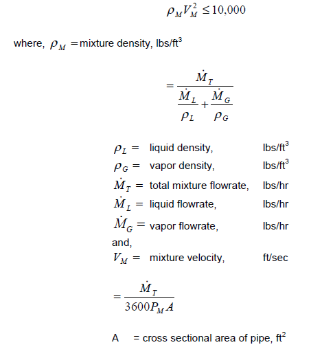
- Piping in intermittent service (for example, startup, pumping–out, bypasses) shall be sized on the basis of available pressure differentials and subject to the line sizing criteria of this Practice.
- Pipe size restrictions on bore and outside diameter are specified in EP 5–2–1.
- Pump suction line sizes shall be determined as follows:
- (*)Pump suction lines shall be sized to provide an available net pump suction head (NPSHA) not less than that required by the pump selected (NPSHR). The NPSHA shall be at the rated pump capacity. The economics of increasing line size versus adjusting vessel elevation shall be considered in providing sufficient NPSH. The line shall not be smaller than the pump nozzle and velocity shall not exceed 10ft/sec. Line velocities higher than 6 ft/sec require approval of the Owner’s Engineer.
- The static head used in calculating the available NPSH shall be measured from the bottom tangent line for vertical vessels, or the bottom of horizontal vessels to one of the following:
- The centerline of a horizontal centrifugal pump or rotary pump.
- The suction nozzle on a vertical centrifugal pump or reciprocating pump.
- The design of storage tank suction lines shall be based on an NPSH taken from the lowest specified liquid level in the tank at which rated pump capacity is required. If vortex–breaking equipment is required, the pressure drop through the equipment shall be considered.
- In sizing suction lines for reciprocating pumps, acceleration head shall be considered.
- The pressure drop available for control valves shall be as specified in EP 5–3–17.
- In areas where the level of noise is a concern, the requirements of IPE ENGINEERING SERVICES Recommended Environmental Guidelines shall be followed.
- Piping Line Lists
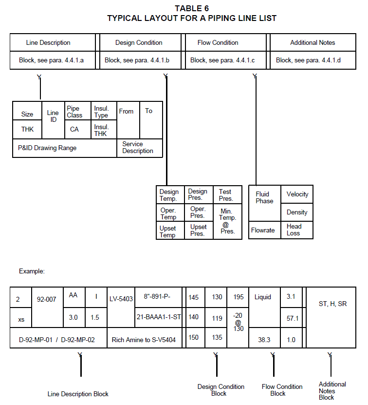
- (*)Unless otherwise specified by the Owner’s Engineer, the Piping Line List (PLL) shall contain the following information for each line.
- Line Description:
- Line number per this Practice, including; the nominal pipe size, unit identifier, line service symbol, line sequence number, IPE standard piping class per EP 5–2–3, and insulation code.
- Pipe thickness (inches) schedule identification and specified corrosion allowance (inches).
- Origin and termination points.
- P&ID drawing number range with contains the referenced line.
- Service description.
- Design Conditions:
- Design pressure (psi) and temperature ( F)
- Normal operating pressure (psi) and temperature ( F)
- Upset pressure (psi) and temperature (F) per this Practice.
- Test pressure (psi) (indicate hydrostatic or pneumatic)
- Minimum design temperature (F) and coincident pressure (psi).
- Flow Conditions:
- Fluid phase description: Liquid, vapor, mixed or two–phase, or slurry.
- Velocity (ft/sec) and flow rate (lbs/hr)
- Density (lbs/ft3)
- Computed head loss (lbs/in2/100ft)
- Additional Notes:
- Identifier to indicate steam traced (ST) or electrical traced (ET) lines.
- Identifier to indicate hydrostatic (H) or pneumatic (P) pressure test.
- Identifier to indicate a stress relieved line (SR).
- Identifier to indicate underground coated and wrapped pipe (CW).
- Identifier to indicate if no flow (NF) in the line during normal operation.
- Identifier to indicate whether or not the line will be subject to a piping stress analysis (SA).
- Identifier to indicate whether the fluid contained is a dangerous material (DM).
- Identifier to indicate whether the installed pipe wall thickness has been calculated for the design pressure–temperature (CWT). Note, CWT will be used when the actual pipe temperature–pressure rating is less than the Full–Flange Rating or “Calculated” is specified in existing IPE Piping System.
- (*)A typical layout for a piping line list is shown in Table 6. Alternative formats for this table may be used if the alternate table contains the same information and approval is obtained from the Owner’s Engineer.
- (*)The following information shall be shown on supplemental data sheets, see EP 5–1–3; or on stress isometrics when the format has been reviewed and approved by the Owner’s Engineer:
- Piping metal temperatures used for piping stress analysis (indicate more than one temperature if multiple temperature conditions apply).
- Identify the governing condition for piping design - such as maximum or minimum operating temperature; equipment steam–out or line steam–out; line bypassed; regeneration; decoking, steam tracing, tank nozzle rotation; etc.
- Piping Layout and Arrangement
Requirements governing general layout and arrangement features for piping systems is covered in EP 5–1–2.
- Piping Stress Analysis and Supports
Requirements for stress analysis of piping systems and design and location requirements for piping supports is covered in EP 5–1–3.
- Standard Piping Supports
Design and Fabrication details for standard piping supports such as shoes, trunions, guides and anchors are covered in EP 5–1–4.
- Piping System Line Numbering
Requirements for numbering piping systems are covered in EP 5–1–5.
PIPING SELECTION AND PURCHASE GUIDELINES
- Selection of Piping Components and Materials
- Basic requirements for the selection and application of piping components and materials for liquid fuel plants, petrochemical plants, and similar industrial installations are covered in EP 5–2–1.
- The requirements in EP 5–2–1 establish the basis for the IPE Piping Standards, and shall be followed when additions, changes, or new specification standards are necessary. The IPE Piping Standards are listed in EP 5–2–3.
- Flanges, Gaskets and Bolting
- Requirements governing the selection of flanges, flange facings, gaskets, bolting, and the design of flanged joints for piping are covered in EP 5–2–2.
- The requirements of EP 5–2–2 establish the general basis for the IPE Piping Standards and shall be followed when additions or changes are necessary.
- Orifice flanges are not within the scope of this Practice.
- IPE Piping Standards
The selection of pipe and piping components for general service categories are covered in EP 5–2–3.
- Supplemental Requirements for Pipe and Piping Components
Supplemental requirements including data to be furnished by the Purchaser, the Manufacturer’s responsibility, documentation, marking, packaging and shipping for pipe and piping components are covered in EP 5–2–4. This Practice shall be used in conjunction with EP 5–2–3 to purchase these components.
- Valve Data Sheets
Valve data sheets for all valves contained in IPE Piping Standards, see EP 5–2–2, are provided in EP 5–3–2. The data sheets included in this Practice are suitable for procurement and should be included in all Purchase Orders for valves. In addition, criteria for
completing valve data sheets for specialty valves (safety valves, reformer MOV’s and FCCU slide valves) are given in the respective valve Practices. Requirements for Hydrofluoric Acid (HF) Service for the Phillips process are covered in EP 5–10–1.
- Metal Flexible Hose
Mandatory requirements governing the design, fabrication, inspection, testing, and installation of metal flexible hoses are covered in EP 5–4–4.
VALVES
- Valve Design and Selection Criteria
- Requirements governing the design and selection of valves, including the use of single and double block valves are covered in EP 5–3–1.
- Specific valve design requirements and general purchase requirements are covered in supplemental practices.
- Steel Gate Valves
Requirements governing the design and inspection of steel gate valves furnished to API 600 and Corrosion Resistant Valves furnished to API 603 are covered in EP 5–3–3.
- Cyclic Reformer Motor Operated Valves
Requirements governing the design, inspection and testing of cast or fabricated (wrought or forged) cyclic reformer motor operator valves are covered in EP 5–3–13.
- Compact and Extended Body Steel Gate and Globe Valves
Requirements governing the design and inspection of compact and extended body steel gate and globe valves furnished to API 602, in sizes NPS 2 and smaller, with threaded, socket welding, or extended butt welding ends are covered in EP 5–3–6.
- Ductile Iron Valves
Requirements governing the design and inspection of flanged ductile iron gate valves furnished to API 604 are covered in EP 5–3–4.
- Steel Globe Valves
Requirements governing the design, inspection, and testing of steel flanged or buttwelding end globe valves are covered in EP 5–3–5.
- Bellows Seal Valves
Requirements governing the design inspection and testing of Bellows Seal gate and globe valves in sizes NPS 2 and smaller, with threaded, socket welding, or extended butt welding end are covered in EP 5–3–7.
- Check Valves
Requirements governing the design, inspection and testing of steel or ductile iron, single and dual plate check valves per API 594 are covered in EP 5–3–8.
- Plug Valves
Requirements governing the design, inspection and testing of hard or soft–seated steel and ductile iron plug valves per API 599 are covered in EP 5–3–9.
- Ball Valves
Requirements governing the design, inspection and testing of steel ball valves per API 608 are covered in EP 5–3–10.
- Butterfly Valves for Hydrocarbon Service
Requirements governing the design, inspection and testing of high performance butterfly valves for hydrocarbon service per API 609 are covered in EP 5–3–11.
- Butterfly Valves for Water Service
Requirements governing the design, inspection and testing of butterfly valves for water service are covered in EP 5–3–12.
- FCCU Slide Valves
Requirements governing the design, inspection and testing of FCCU Slide Valves are covered in EP 5–3–19.
- Pressure Relief Valves
- Requirements governing the design, inspection and testing of pressure relief valves are covered in EP 5–3–14.
- Sizing requirements and use of pressure relief valves are stipulated in EP 3–7–1.
- Control Valves
Requirements governing the design, inspection and testing of control valves are covered in EP 5–3–17.
- Supplemental Requirements for Valves
Supplemental requirements including data to be furnished by the Purchaser, the Manufacturer’s responsibility, documentation, marking, packaging and shipping for valves are covered in
EP 5–3–21. Specific requirements for each valve type are provided in a separate Practice.
- Three Way Valves
Requirements for three–way valves are covered in EP 5–3–16. Tandem pressure relief valves (PRV), which are designed to insure that one pressure relief valve in the tandem set is open while the other is isolated for maintenance and/or testing, are covered in this Practice.
- Valve Packing
Requirements covering stem packing for valves are covered in EP 5–3–23.
- Valve Inspection and Testing
Requirements for inspection and testing of valves are covered in EP 5–3–24. These requirements include: procedures for pressure testing, material hardness limitations for valves in Aggressive Environmental Services, and casting quality and inspection guide and inspection guidelines for valves.
- Flue Gas Block and Bypass Valves
Requirements governing the design, inspection and testing of flue gas block and bypass valves are covered in EP 5–3–18.
- Double Flanged High Performance Rotary Valves for Hydrocarbon Service
Mandatory requirements governing the design, inspection, and testing of double flanged rotary valves (butterfly) for hydrocarbon service are covered in EP 5–3–20.
- Valve Reconditioning - Gate, Globe, Check, Ball and Plug Valves
Requirements covering valve reconditioning of manual valves are covered in EP 5–11–5.
- Valve Reconditioning - Pressure Relief Valves
Requirements covering valve reconditioning of pressure relief valves (PRV) are covered in EP 5–11–6.
- Valve Reconditioning - FCCU Slide Valves
Requirements covering valve reconditioning of FCCU slide valves are covered in EP 5–11–7..
EXPANSION JOINTS
- Metal Expansion Joints
Requirements governing the design, fabrication, inspection, and testing of circular and rectangular metal bellows expansion joints are covered in EP 5–4–1.
- Fabric Expansion Joints
Requirements governing the design, fabrication, inspection, and testing of circular and rectangular fabric expansion joints are covered in EP 5–4–2.
- Supplemental Requirements for Expansion Joints
Supplemental requirements including data to be furnished by the Purchaser, the Manufacturer’s responsibility, documentation, marking, packaging and shipping for metal and fabric expansion joints are covered in EP 5–4–3.
PIPING FABRICATION, WELDING, ERECTION AND TESTING
- Piping Fabrication
- Requirements for shop and field fabricated piping, and inspection of piping assemblies, including expansion joints, furnace headers and furnace tube assemblies are covered by EP 5–5–1.
- Selection of piping components and materials, other than furnace tube materials, are covered in EP
5–2–1. Selection of furnace tube materials is covered in EP 8–2–1.
- Welding Requirements for Piping
Requirements for welding of piping assemblies are covered in EP 5–5–2. Additional requirements for seal welding and welding of pipe supports are also covered by this Practice.
- Piping Erection and Testing
Requirements for field erection, testing, inspection, and cleaning of fabricated metallic piping are covered in EP 5–5–3.
- Supplemental Requirements for ASME Code Section I Piping
Supplementary requirements for ASME Code Section I Piping associated with Power Boilers are covered by EP 5–5-8.
- Supplemental Requirements for Jacketed Piping
Supplemental fabrication requirements for jacketed piping systems are covered in EP 5–5–5.
- Supplemental Requirements for Fabricated Piping
Supplemental requirements including data to be furnished by the Purchaser, the Manufacturer’s responsibility, documentation, marking, packaging and shipping for shop or field fabricated piping assemblies are covered in EP 5–5–6. This Practice shall also be used for the purchase of furnace tube coils.
- Supplemental Requirements for Pneumatic Testing of Piping Systems
Supplemental pneumatic testing requirements for piping systems constructed to the ASME B31 Piping Codes are covered in EP 5–5–7.
HOT TAPS AND TIE–INS
- Hot Taps
Requirements governing the design, location, inspection and testing of pressure tap connections (hot taps) on piping, pressure vessels, and tankage are covered in EP 5–7–1.
- Tie-Ins
Requirements governing the design and inspection and testing of tie–ins for new piping systems are covered in EP 5–7–2.
10.0 PIPING FOR ATMOSPHERIC STORAGE TANKS AND LOW PRESSURE STORAGE VESSELS
Requirements governing the design, layout and arrangement of piping connected to atmospheric storage tanks or low pressure storage vessels are covered in EP 5–6–1.
PIPING AND STRAINERS FOR ROTATING EQUIPMENT
- Piping for Rotating Equipment
Requirements governing the design, fabrication, inspection and testing of the following piping systems are covered in EP 5–6–2
- Suction and discharge piping for Centrifugal Pumps.
- Centrifugal Compressor Piping.
- Reciprocating and Positive Displacement Compressor Piping.
- Steam Turbine Inlet and Exhaust Piping.
- Flushing and drain connections for centrifugal and rotary compressors.
- Washing systems for steam turbines.
- Auxiliary Piping for Rotating Equipment
Design, fabrication, installation and inspection requirements of auxiliary piping associated with compressors, centrifugal fans, turbines, engines, gears, and pressurized lube and seal oil systems are covered in EP 5–6–2.
- Strainers for Rotating and Other Equipment
Requirements governing the design and application of temporary and permanent strainers for the protection of equipment are covered in EP 5–4–5. This basic Practice does not cover metal screen or porous media filters with openings finer than 150 mm.
12.0 PIPING FOR FIRED HEATERS
Requirements governing the design, layout and arrangement of piping systems connected to fired heaters, including fuel gas systems, are covered in EP 5–6–3.
REQUIREMENTS FOR IN–SERVICE PIPING SYSTEMS
- Inspection, Repair, Alteration, and Rerating of In-Service Piping Systems
Requirements for inspection, repair, alteration, and rerating of in–service piping systems are covered in EP 5–11–2. This Practice is a supplement to API 570.
- Requirements For On–line Leak Repairs
Requirements for performing on–stream repairs leaks in flanges and valve packing are covered in EP 5–11–3. In addition, the on–stream repairs for pipe flanges covered in EP 5–11–3 can be used for pressure vessel nozzle and girth flanges.
- Installation of Repair Patches and Sleeves
Requirements governing the design and installation of surface repair patches and sleeves that are fillet welded directly to the pipe, and flush insert patches that are butt welded directly to the pipe, and flush insert patches that are butt welded to the pipe are covered in EP 5–11–4. The requirements of EP 5–11–4 apply to damaged areas that are either in–service or out–of–service and are not leaking.
- Evaluation and Reuse of In-Service Piping Systems
Requirement covering the evaluation and reuse of in-service piping systems constructed to the ASME B31 Piping Codes are covered in EP 5–11–2.
PIPING FOR STEAM SYSTEMS
- Steam Piping
Requirements governing the design, layout and arrangement of steam piping systems are covered in EP 5–6–6.
- Steam Traps
Requirements for the selection and use of steam traps are covered in EP 5–6–7.
- Steam Tracing
Requirements governing the design, layout and arrangement of steam tracing systems are covered in EP 5–6–8.
GUIDELINES FOR PRESSURE RELIEF PIPING SYSTEMS
- Piping for Pressure Relief Systems
- The design of pressure relief piping systems is covered in EP 3–7–1.
- Additional requirements governing the design, layout and arrangement of pressure relief piping systems are covered in EP 5–6–4.
- Rupture Disk Devices
- General requirements for the use of and design of rupture disk devices are covered in EP 3–7–1.
- Additional design requirements and a specification sheet for rupture disk devices are included in EP 5–3–15.
PIPING FOR INSTRUMENTS
- General requirements for instrumentation piping systems are covered in EP 12–1–1.
- Additional requirements covering the design of instrumentation piping systems are covered in EP 5–6–5.
- General installation details for instruments and their associated piping systems are shown in EP 12–2–1.
17.0 PIPING AND DESIGN OF MANUAL SAMPLING SYSTEMS
Requirements governing the design, layout and arrangement of piping and manual sampling systems are covered in EP 5–8–1.
DESIGN AND INSTALLATION OF NON–METALLIC PIPE
- Requirements governing the design and installation of non–metallic pipe are covered in EP 5–9–1.
- Requirements governing the design and installation of plastic lined metallic pipe are covered in EP 5–9–2.
19.0 DESIGN AND INSTALLATION OF CEMENT LINED PIPE
Requirements governing the design and installation of cement lined pipe and fittings are covered in EP 5–9–3.
SUPPLEMENTAL REQUIREMENTS FOR PIPING IN HF SERVICE
- Supplemental Requirements for Piping in HF Service (Phillips)
Supplemental requirements for piping in HF service for the Phillips process are covered in
EP 5–10–1. The format of this recommended practice closely follows the Phillips HF Specification to facilitate use with existing facilities.
- Supplemental Requirements for Piping in HF Service (UOP)
Supplemental requirements for piping in HF service for UOP process are covered in
EP 5–10–2. The format of this recommended practice closely follows the UOP HF Specification to facilitate use with existing facilities.
TABLES
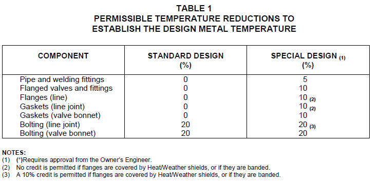
TABLE 2
LINE SIZING CRITERIA FOR LIQUIDS
| Service | Normal Range Pressure Drop (psi/100 ft) | Velocity (ft/sec) | Velocity (ft/sec) |
|---|---|---|---|
| Normal | Maximum | ||
| Pump Suction, Boiling (1) Pump Suction, Subcooled (1) Pump Discharge, General (1) | 0.05–0.25 (2) 0.2–0.75 (2) 1.4–3.5 |
3 (3) 6 (3)(7) 10 |
5 (3) 10 (3) 20 (6) |
| Cooling Water Headers Cooling Water Branches | 0.5 2.0 |
10 10 |
20 (4) 20 (4) |
| Liquid to Thermosiphon Reboiler | 0.2 | 4 | — |
| Side–Stream Drawoff | 0.05–0.25 | 4 (3) | 10 (3) |
| Amine, Carbonate, and Sour Water (prevent flashing) | — | 7 | — |
| Sulfur, Pumped Sulfur Gravity | 0.5–3.0 | 10 2.5 |
— |
| Sulfuric Acid (except as noted) Sulfuric Acid 93% to 99.6% (steel) less than 120F |
— — |
— — |
5 1 |
| Hydrofluoric Acid (carbon steel) | — | — | 10 |
| Sodium Hydroxide, up to 30% 30% to 50% 50% to 73% |
— — — |
6 5 4 |
— — — |
| Sulfur Slurry | — | — | 4 (5) |
NOTES:
- (*)Do not use average flow rates with positive displacement pumps. If suction piping is complex, use 1 ft/sec unless otherwise specified by the Owner’s Engineer.
- NPSH requirement is the major criterion for sizing pump suction lines.
- The vessel suction nozzle size is often set by velocity limits to prevent vortexes. The line must be configured so that there is at least 5 vertical feet from the nozzle, at the nozzle size, before reducing the size of the line.
- Check effect of water hammer before using maximums.
- Square duct 1/3 full.
- Use 10 ft/sec for NPS 4 and smaller, 15 ft/sec for NPS 6 through NPS 12, and 20 ft/sec for NPS 14 and larger.
- (*)Velocities greater than 6 ft/sec require Owner’s Engineer approval.
TABLE 3
SIZING CRITERIA FOR GASES AND STEAM
| Service | Normal Range Pressure Drop (psi/100 ft) | Velocity (ft/sec) | Velocity (ft/sec) |
|---|---|---|---|
| Normal | Maximum | ||
| General Gases and Vapors Less than 15 psia (vacuum) Up to 100 psig 100 psig to 1,000 psig Over 1,000 psig |
0.05–0.25 (1) 0.25 - 0.50 (1) 0.50–2.0 (1) 0.2% P (1) |
200 - 250 150 - 200 100 - 150 100 |
50% Vs (2) 50% Vs (2) 50% Vs (2) 50% Vs (2) |
| SO2 and SO3 Process Gas | — | 50 - 90 | - |
| Compressor Suctions Reciprocating Centrifugal | % P % P |
20 - 40 40 - 80 |
7% Vs (2) 13% Vs (2) |
| Steam | |||
| Saturated, less than 50 psig | 1%P (1) | ||
| 50 d | 100 d (3) | ||
| 50 psig to 250 psig | 0.6–1.3 (1) | ||
| 40 d | 100 d (3) | ||
| 250 psig to 1,000 psig | 1.3–3.0 (1) | ||
| 30 d | 100 d (3) | ||
| Superheated, above 250 psig | 0.7% P | ||
| 50 d | 100 d (3) | ||
| Superheated, less than 250 psig | (4) | (4) | (4) |
NOTES:
- These values are for headers within plant limits; short branch lines may be sized for two to three times the friction loss in this table.
- Sonic or acoustic velocity, where:
Vs , sonic velocity (ft/sec) g = 32.17 (lb–ft)/ (lbf–sec 2 )
k = Specific Heat Ratio Cp/Cv
Z = Compressibility Factor R = 1546(ft–lbf)/(lbmole– R)
T = Absolute Temperature, R Mw = Molecular Weight
- These velocities will usually be applied only to short branches. Their use for headers will result in very high friction loss.
d = nominal diameter in inches
P = Operating Pressure (4) Same as gases and vapors
- Same as gases and vapors
TABLE 4
LINE SIZING CRITERIA FOR FLUID SOLIDS LINES
| Service | Description | Maximum Velocity (ft/sec) |
|---|---|---|
| Catalyst Standpipes | Dense - Phase Flow | 5.5 |
| Catalyst Carrier Lines | Dilute - Phase Flow, Solid Density ≥ 0.5 lbs/ft3 | 40 |
| Dilute – Phase Flow Solid Density> 0.5 lbs/ft3 |
80 | |
| FCCU Flue Gas Lines | Solid Density< 0.1 lbs/ft3 | 120 |
TABLE 5
LINE SIZING CRITERIA FOR MIXED PHASE FLOW
| Service | Description | Maximum Velocity (ft/sec) |
|---|---|---|
| Liquid, Gas or Vapor Mixture Lines | General | 75 (1) |
| Liquid, Gas or Vapor Mixture Lines | Reboiler Outlet | 40 (2) |
| Solid Liquid Lines | Slurry | 8 (3) |
NOTES:
- See paragraph 4.3.4.
- Velocity must be sufficient to carry condensed liquids along with vapors.
- Minimum velocity of 3 ft/sec.
© 2026 Inflection Point Engineering, LLC. All rights reserved. The content of this page — including calculation methods, reference data, written analysis, interactive tools, and source code — is the intellectual property of Inflection Point Engineering, LLC and is protected under applicable copyright, trademark, and trade secret laws. Unauthorized reproduction, redistribution, modification, or derivative use in whole or in part is prohibited without prior written consent.
Disclaimer. This material is provided for informational and educational purposes only and does not constitute professional engineering advice. Calculations, reference data, and methodologies are based on published standards and accepted engineering practice but are not a substitute for engineering judgment, site-specific analysis, or review by a licensed Professional Engineer. Inflection Point Engineering, LLC makes no warranties, express or implied, regarding the accuracy, completeness, or fitness for a particular purpose of any content presented here, and shall not be liable for any direct, indirect, incidental, or consequential damages arising from its use. Users assume all risk associated with applying this content to real-world design, operations, or decisions.
© 2026 Inflection Point Engineering, LLC. All rights reserved.