 Section 4 — Structures and Foundations
Typical Sewer Details
IPE Engineering Practice IPE-EP-4-8-2
Document number: IPE-EP-4-8-2 · Section: 4 — Structures and Foundations
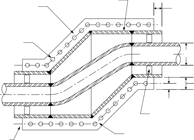
Figure 19 Double-Walled Wyes Retrofit 36
Figure 20 Double-Walled Pipe Tees Retrofit 37
Figure 21 Clamped End Connectors Retrofit 38
SCOPE
- This Practice provides supplemental details for the design of general and special sewer systems. Basic requirements for sewer systems and special sewers are covered in EP 4-8-1 and EP 4-8-3.
- Any deviation to this Practice must be approved by the procedure described in EP 1-1-3.
- An asterisk (*) indicates that a decision or approval by the Owner's Engineer is required, or that additional information is furnished by the Purchaser.
- A revision bar indicates all changes made to this Revision.
- Documentation required in accordance with this Practice is given in Table 1.
2.0 REFERENCES
The latest edition of the following standards and publications are referred to herein.
STANDARDS AND PUBLICATIONS
| IPE Engineering Practices | IPE Engineering Practices |
|---|---|
| EP 1-1-3 | Deviations to IPE Engineering Practices |
| EP 4-2-2 | Earthwork |
| EP 4-2-7 | Foundations for Atmospheric Storage Tanks |
| EP 4-2-10 | Atmospheric Storage Tank Foundation Monitoring, Repair and Retrofit |
| EP 4-3-1 | Concrete Design |
| EP 4-3-2 | Concrete Construction Requirements |
| EP 4-4-1 | Roadways and Paving |
| EP 4-5-1 | Structural Steel |
| EP 4-5-3 | Auxiliary Structures for Operation and Maintenance |
| EP 4-8-1 | Sewer Systems |
| EP 4-8-3 | Special Sewer Systems |
| EP 5-1-3 | Piping Stress Analysis and Supports |
| ASME/ANSI | ASME/ANSI |
| B16.9 Factory-Made Wrought Steel Buttwelding Fittings | B16.9 Factory-Made Wrought Steel Buttwelding Fittings |
| ANSI/AWWA | ANSI/AWWA |
| A21.10/C110 A21.11/C111 |
Ductile Iron and Gray Iron Fittings 3 in. through 48 in.for Water and Other Liquids Rubber Gasket Joints for Ductile-Iron and Gray-Iron and Pressure Pipe and Fittings |
STANDARDS AND PUBLICATIONS (CONT.)
| ANSI/AWWA (Cont.) |
|---|
| A21.53/C153 Ductile Iron Compact Fittings, for Water or Other Liquids M9 Concrete Pressure Pipe |
| API |
| 650 Welded Steel Tanks for Oil Storage |
| ASTM |
| C443 Joints for Circular Concrete Sewer and Culvert Pipe, Using Rubber Gaskets C478 Precast Reinforced Concrete Manhole Sections |
DEFINITIONS
- Aboveground sewer system - Sewer system with the majority of piping installed above grade on pipe supports or in covered, lined trenches. Sumps and buried piping may be required immediately beneath process drains and surface drainage areas.
- Catch basin - An open basin that collects stormwater runoff from Plant surfaces and Plant wastewater from process drains.
- Closed sewer system - Sewer system maintained under positive or negative gage pressure, venting to an emissions control system.
- Double-walled Sewer System - Sewer system whose components have a secondary wall or liner outside of the primary wall, to protect the subgrade from leaks and to provide an annulus for leak detection.
- Fire seal - means of preventing the movement of a flame front in the vapor space of a partially filled pipeline, also referred to as a fire stop.
- Junction Box - A manhole or other access to a wastewater sewer line system.
- Manhole - Cased hole that allows bodily access to a sewer system through a covered hatch on top.
- Manufacturer - The recipient of a direct or indirect purchase order for materials and/or equipment. In this context, a direct order is one issued to a manufacturer by a contractor or the Owner. An indirect order is one issued to a manufacturer by a vendor (recipient of a direct order) for materials, fabricated components, or subassemblies.
- Owner - Inflection Point Engineering, LLC.
- Owner's Engineer - A Inflection Point Engineering, LLC appointed engineer.
- Vapor Seal - A water seal to prevent the escape of vapor from sewers containing volatile organic compounds (VOCs).
4.0 MATERIALS
- Acceptable materials for sewer piping components and material standard references are given in Table 1 and Table 2 of EP 4-8-1 and EP 4-8-3.
- Concrete and concrete reinforcement materials used in sewer installations shall be in accordance with EP 4-3-1.
- Structural steel used in sewer installations shall be in accordance with EP 4-5-1.
- Outer piping components of buried double-walled sewer systems shall be in accordance with Table 2 of EP 4-8-1.
5.0 PIPING COMPONENTS
- Single-walled piping components shall comply with the referenced standards given in Section 4.0.
- (*)Double-walled piping components, including pipe, tees, offsets, wyes, elbows and caps shall be designed in accordance with the details illustrated in Figures 1A through Figure 7. The use of alternative commercial piping component designs, including drains, satisfying the intent of the designs given in this Practice is subject to the approval of the Owner's Engineer.
6.0 CATCH BASINS
(*)Catch basin designs shall be in accordance with the applicable details in Figures 8A, 8B, 8C and Figures 9A and 9B. The use of alternative commercial catch basin designs satisfying the intent of the designs in this Practice is subject to approval of the Owner's Engineer.Figures 8A, 8B, 8CFigures 9A 9B.
7.0 MANHOLES
(*)Manhole designs shall be in accordance with applicable details in Figures 10A and 10B and Figures 11A and 11B. The use of alternative commercial manhole designs satisfying the intent of the designs given in this Practice is subject to the approval of the Owner's Engineer.Figures 10A10B Figures 11A 11B
8.0 THRUST BLOCKS
- Thrust block configuration shall be in accordance with the applicable detail given in Figure12.
- Thrust block sizing shall be in accordance with EP 5-1-3.
9.0 SUMPS
- (*)Sumps in aboveground sewer systems designed per EP 4-8-3 shall be in accordance with the details in Figure 13 . Alternative sump designs for aboveground sewers are subject to the approval of the Owner's Engineer.
- (*)Lift station designs are subject to the approval of the Owner's Engineer.
10.0 PIPE TRENCHES
(*)Trenches for aboveground sewers designed per EP 4-8-3 shall be in accordance with Figure 14A and 14B.Figure14A 14B
11.0 DOUBLE-WALLED RETROFITS
- (*)Double-walled retrofits for installed piping components shall be in accordance with Figure 15 through Figure 21. The use of alternative commercial retrofit designs for double-walled sewer components that satisfy the intent of this Practice is subject to the approval of the Owner's Engineer.
- (*)Bolting materials for buried double-walled retrofit components shall be plastic or coated carbon steel, unless otherwise approved by the Owner's Engineer.
12.0 JOINTS
- (*)The inner pipe of double-walled sewer lines shall have welded or bolted mechanical joints unless otherwise specified by the Owner's Engineer.
- (*)The outer pipe of double-walled sewer lines shall have welded, bolted mechanical, o-ring or flanged joints unless otherwise specified by the Owner's Engineer.
13.0 TABLES
TABLE 1 DOCUMENTATION REQUIREMENTS
FOR TYPICAL SEWER DETAILS PER EP 4-8-2
| Item | Description | Format | As-Built |
|---|---|---|---|
| 1 | Drawings and specifications for alternative designs, submitted for approval in accordance with this Practice | See EP 2-5-2 | Yes |
14.0 FIGURES
FIGURE 1A
DOUBLE-WALLED PIPE SEGMENTS LONG RUNS OF CONSTANT DIAMETER
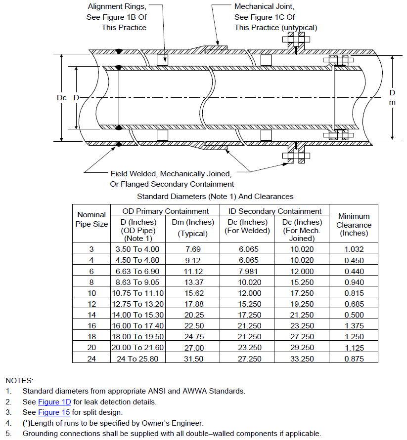
FIGURE 1B ALIGNMENT RINGS
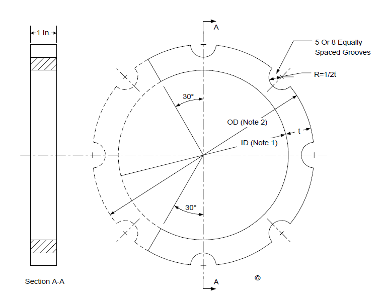
NOTES:
- ID = OD primary pipe plus 1/16 inch.
- OD = ID secondary pipe minus 1/16 inch.
- Full-ring (dashed lines) optional with new installations. 240-degree ring shall be used with retrofits.
FIGURE 1C SECONDARY PIPE JOINTS
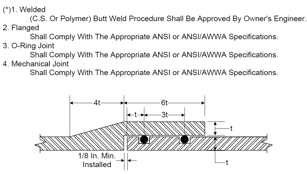
NOTES:
- Seal, gasket and O-ring material shall be suitable for all expected fluid services.
- Seal, gasket and O-ring grooves shall be dimensioned in accordance with manufacturer's recommendations.
- O-rings shall be 3/16 inch nominal diameter or greater.
- Surface finish of O-ring grooves shall be 63 rms.
FIGURE 1D LEAK DETECTION
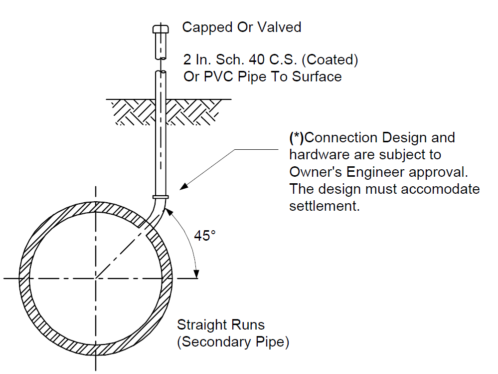
NOTES:
- Pipes to surface shall be spaced a maximum of 100 feet.
- (*)Pipes to surface can be used with any of the following leak detection systems. The Owner shall approve selection of leak detection system.
a.) Pressure held in annulus. b.) Fluid or vapor sensing.
c.) Electric wire routed through grooves in alignment rings.
FIGURE 2
DOUBLE-WALLED SHORT RUNS AND OFFSETS
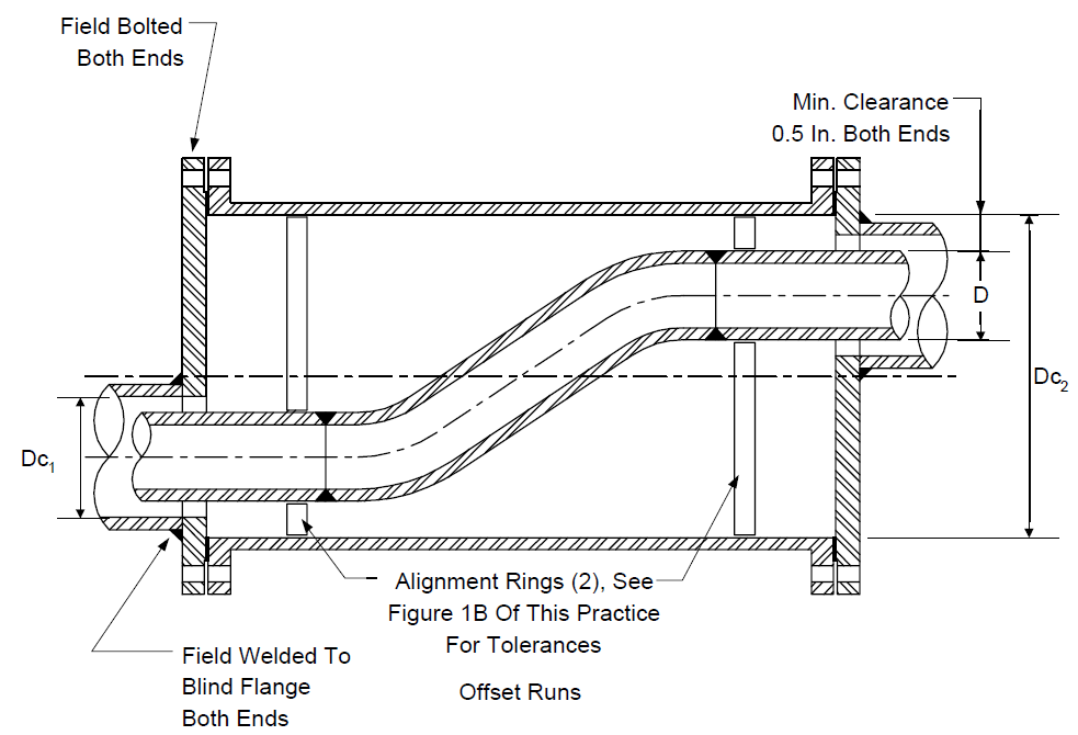
NOTES:
- See Figure 1A for diameter dimensions.
- For Dc2 required greater than four times D, see Figure 16. See also Figure 16 for split design.
- Use similar oversize pipe for short runs with reducers.
- Short runs shall be defined as length of run less than ten times primary pipe diameter.
- For short run with reducer, blind with offset secondary pipe shall be replaced by welding neck or reducing flange, as appropriate.
- See Figure 1D for leak detection details.
FIGURE 3
DOUBLE-WALLED REDUCERS
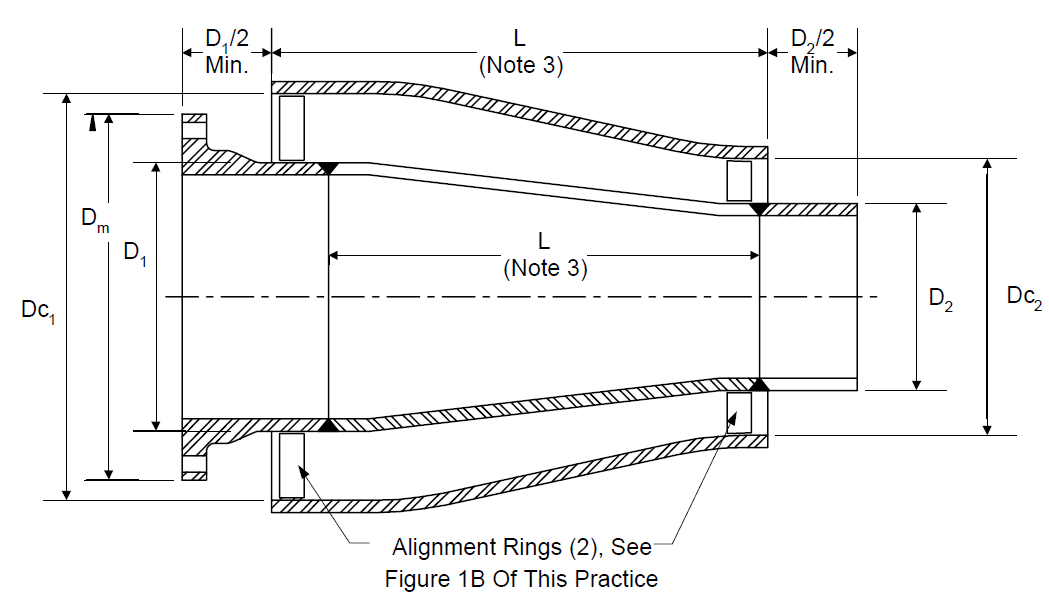
NOTES:
- See Figure 1A for required clearances and matching diameters for primary and secondary components.
- See Figure 17 for split design.
- See Figure 1D for leak detection details.
- See ANSI/ASME B16.9 and ANSI/AWWA A21.10/C110 and A21.11/C111 for typical lengths of standard reducers.
- If reducer is part of a short run, where the length of the run is less than 10 times the primary pipe diameter, the detail in Figure 2 shall be used.
- Reducer assembly shall be shop fabricated.
FIGURE 4A DOUBLE-WALLED ELBOWS


- Larger Elbow
NOTES:
- See Figure 4 for alternate, mitered, design.
- Elbow assembly shall be shop fabricated.
- See Figure 1A for required clearances and matching diameters for primary and secondary components.
- See Figure 1D for leak detection details.
- For short radius primary elbow, use short radius secondary elbow. For long radius primary elbow, use long radius secondary elbow.
5. See Figure 18 for split design.
FIGURE 4B DOUBLE-WALLED ELBOWS
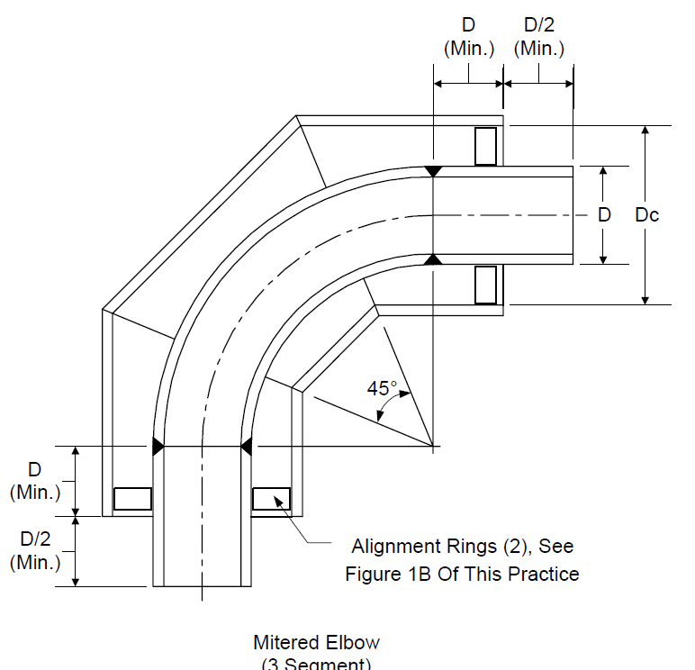
NOTES:
- See also Notes on Figure 4.
- Use two-segment miter on 45-degree elbow.
- See Figure 18 for split design.
- Mitered elbow assembly shall be shop fabricated.
FIGURE 5 DOUBLE-WALLED WYES
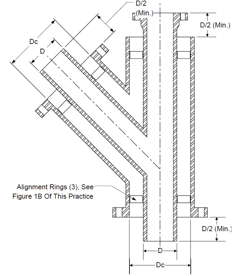
NOTES:
- See Figure 1A for required clearances and matching diameters for primary and secondary components.
- Wye assembly shall be shop fabricated.
- See Figure 1D for leak detection details.
- See ANSI 21.11/AWWA C111 for dimensions of standard wyes.
- See Figure 19 for split design.
FIGURE 6
DOUBLE-WALLED PIPE CAPS
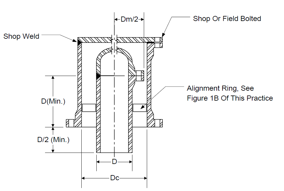
NOTES:
- Bolted caps shall be used where access is required for inspection.
- See Figure 1A for required clearances and matching diameters for primary and secondary components.
- See Figure 1D for leak detection details.
- Cap assembly shall be shop fabricated.
- See ANSI/ASME B16.9 and ANSI/AWWA A21.53/C153 for dimensions of standard caps.
- This double walled cap design shall apply to retrofits.
FIGURE 7
DOUBLE-WALLED PIPE TEES


NOTES:
- See Figure 1A for required clearances and matching diameters for primary and secondary components.
- See Figure 1D for leak detection details.
- See Figure 20 for split design.
- Tee assembly shall be shop fabricated.
- See ANSI/ASME B16.9 and ANSI/AWWA A21.53/C153 for dimensions of standard tees.
FIGURE 8A CATCH BASINS


Neenah Or Owner's
* Engineer Approved Equivalent Frame And
Grating
D
30 In. Max.
18 In. Min.
D=Nominal Diameter Of R/C Cylinder Pipe With Bell And Spigot
Below Frost Line (3 Ft. Min.)
Finished Grade (See Note 7)
4 In.
Min. 2" grout 12 In.
10 In. Square (Formed) R/C Footing
#4 Bars Each Direction,
Equal Spaced. Minimum Number Of Bars Per
Note 3 2D
Direction Shall Be D/6 Reinforced Concrete Cylinder Pipe
NOTES:
- See AWWA M9 for RCCP tapping procedure. Inlets and outlets shall be grouted. Inverts as noted on site drawings.
- See Figure 8B for catch basin with fire seal..
- Compact subgrade in accordance with EP 4-2-2.
- Minimum cover of 3 inches for reinforcement in footing.
- Concrete and reinforcement materials shall comply with EP 4-3-1. Minimum compressive strength of concrete shall be 3000 psi at 28 days.
- Excavation shall be backfilled with granular material, compacted in accordance with EP 4-2-2, to within 6 in. of finished grade.
- Catch basin may be located in concrete slab with flexible joint filler isolation provided.
- (*)Inlet and outlet locations shall be specified in the engineering design.
FIGURE 8B CATCH BASINS


- (*)Neenah Or Owner's Engineer Approved
Equivalent Frame And D
Grating
D=Nominal Diameter Of Precast Segment (In.)
Sections Shall Be Gasketed
In Accordance With ASTM C443
See Note 2 Inlet
Outlet
6 In. Min.
Finished Grade (See Note 6)
Precast Concrete Or Reinforced Concrete Segments In Accordance With ASTM C139 Or C478.
Alternate Geometries Include Concentric Conical And Eccentric Conical Top Segments
Note 3
12 In. Min. Sediment Trap
Square Footing 10 In. Per Figure 8A
Of This Practice
Precast - Sectional
NOTES:
- See AWWA M9 for tapping procedure. Inlets and outlets shall be grouted. Inverts as noted on site drawings.
- (*)Slope of concrete to be specified in engineering design.
- Compact subgrade in accordance with EP 4-2-2.
- Concrete and reinforcement materials shall comply with EP 4-3-1 unless otherwise noted in referenced ASTM specifications. Minimum compressive strength of concrete shall be 3000 psi at 28 days.
- Minimum cover of 3 inches for reinforcement in footing.
- Excavation shall be backfilled in accordance with Figure 8A.
- Catch basin may be located in concrete slab with flexible joint filler isolation provided.
7. (*)Inlet and outlet locations shall be specified in the engineering design.
FIGURE 8C CATCH BASINS


- (*)Neenah Or Owner's Engineer Approved Equivalent Frame
And Grating
Finished Grade Or Concrete Slab
Flexible Joint Filler Isolation
Finished Grade Or Concrete Slab
Square R/C Box 3 Ft. x 3 Ft.
Internal Dimensions
Outlet For "Dry" Basin (See Note 6,8)
3 Ft. - 0 In.
8 In.
See Note 2
12 In.
Waterstop Full Perimeter
Note 3
Cast-In Place Reinforced Concrete
NOTES:
- Reinforcing steel shall consist of #5 bars on 12-inch centers both directions in two layers of base and one layer on side walls. A minimum of 3 inches cover shall be provided for all surfaces in contact with subgrade.
- (*)Slope of concrete to be specified in engineering design.
- Compact subgrade in accordance with EP 4-2-2.
- Concrete and reinforcement materials and construction shall comply with EP 4-3-1 and EP 4-3-2. Minimum compressive strength for Portland cement concrete shall be 3000 psi at 28 days for normal concrete, or 7 days for high-early strength concrete.
- Excavation shall be backfilled in accordance with Figure 8A.
- (*)Inlet and outlet locations shall be specified in the engineering design. Inverts as noted on the site drawings.
- Inlets and outlets shall be grouted.
- Minimum 12" sediment trap is required.
- See Figure 8B for Catch Basin with Fire Seal
FIGURE 9A
DOUBLE-WALLED CATCH BASINS - EXTERNAL CONTAINMENT
Capped Tell-Tale
Pipe In Accordance With RP 4-2-6
Flexible Joint Filler
Neenah Or Owner's


* Engineer Approved Equivalent Frame And Grating
3 In.
12 In.
6 In.
2% Slope
Finished Grade
4 In. Slab
(Note 3)
(Min.)
Field Weld (Note 2)
Flexible
Joint Filler
12 In.
6 In.
Rigid 1/4 In. Thick
* Polymeric Anchor Ring Or Alternate Detail Approved By The Owner's Engineer
Flexible Membrane Liner In Accordance With RP 4-2-6
Backfill (Note 1)
Anchor
3 In. Perforated PVC Drain Pipe On One Side Of Square Excavation (Note 5)
(Gravel Around Drain Pipe)
6 In.
(Min.)
Sub Grade Compacted Sand
(Note 4)
NOTES:
- Backfill shall be in accordance with Note 1 of Figure 28 of EP 4-2-7.
- Welding procedure for all field welds and liner seams shall be qualified per Appendix I of APl 650.
- Slab shall be reinforced in accordance with EP 4-4-1. A 6-inch slab shall be used in areas where there is to be heavy traffic.
- Sand shall be compacted in accordance with EP 4-2-2.
- Drain shall slope 1/48 to one end of side of square excavation, where PVC tell-tale pipe is to be connected.
- Basin design shall be per Figure 8.
- (*)All projections through liner shall be sealed Seal designs shall be approved by the Owner's Engineer.
FIGURE 9B
DOUBLE-WALLED CATCH BASINS - LINED


- (*)Neenah Or Owner's Engineer Approved Equivalent Frame And
Grating
Finished Grade Or Concrete Slab
Finished Grade Or Concrete Slab
Liner Anchors In Grating Frame (Typ.)
Integral Pipe Note5ction
Min. Gap 1 In. For Leak Detection Tube To Surface
Commercial Polymeric Rigid Liner (Min. Wall Thk. = 1/4 In.) Sealed At All Penetrations
Embedded Angles, Tees, Or Grating For Support Of Liner
NOTES:
- Liner may also be used with precast-sectional and RCCP catch basins.
- Liner shall be compatible with all potential fluids that may be collected and transported through the sewer system.
- A minimum of one leak detection port (tube or pipe to surface) shall be installed in the annulus between the basin and liner at the basin's internal low point.
- See Figure 8C for basin details.
FIGURE 10A MANHOLES
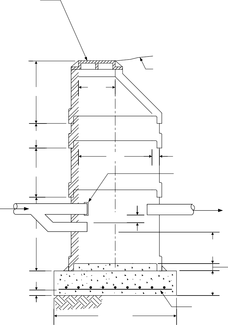
- (*)Neenah Or Owner's Engineer Approved Equivalent Frame And Cover (6 In. Above Grade If Unpaved)
37-1/2 In. (Typ.)
- Ft.-4 In.
- Ft.-8 In.
Finished Grade
24 In. Precast Sections ShallComply With ASTM C478
Sections Shall Be Gasketed In Accordance With ASTM C443
48 In. 5 In. Wall
(Min.)
Vapor Tight Cap Or Plug
Inlet Fire Seal
(Typ.)
4 Ft.
6 In. Min.
Outlet
12 In. Min. Sediment Trap
2 In. Grout Min.
12 In.
Square Footing
3 In.
Cover 6 Ft. - 0 In.
Precast - Sectional
#4 Bars At 6 In. Spacing, Both Directions
NOTES:
- See Notes for sectional catch basin Figure 8B. Inverts as noted on site drawings.
- Ladder to be provided in accordance with ASTM C478.
- Manholes shall be vented per EP 4-8-1.
FIGURE 10B MANHOLES


(*)Neenah Or Owner's Engineer Approved Equivalent Frame And Cover (6 In. Above
Grade If Unpaved) Finished Grade
Or Concrete
8 In.
12 In.
2 Ft.
Elevation
8 Ft. (Typ.)
4 Ft.-0 In. 8 In. Wall (Min.)
Minimum 3 In. Cover All Reinforcement
12 in. min.
12 In.
Waterstop Full Perimeter
5 Ft. - 4 In.
8 In.
5 Ft. - 4 In.
Plan - Top
8 In.
Cast-In Place Reinforced Concrete
NOTES:
1. See Figures 8C and 10A for Notes.
FIGURE 11A
MANHOLES - EXTERNAL CONTAINMENT


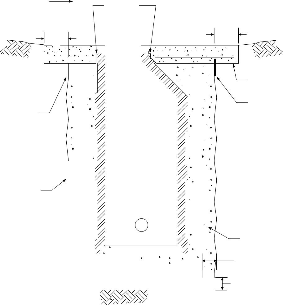

Capped Tell-Tale Pipe (Note 1)
Finished Grade
12
In.
Flexible Joint Filler & Seal
12
In.
Finished Grade
3 In.
(Min.
)
Field Weld (Note 1)
4 In. Slab
(Note 1)
Rigid Anchor Ring (Note 1)
Flexible Membrane Liner (Note 1) (Complete Encasement Required)
Anchor
Perforated Drain (Note 1)
Fill (Note 1)
6"
Minimum (Typ.)
6 In.
(Min.
)
Sand (Note 1)
NOTES:
- See Figure 9A for notes and details.
- See Figure 10 for manhole details.
FIGURE 11B
DOUBLE-WALLED MANHOLES LINED

Grade Or Slab
Liner Anchors In Wall (Capped)
Min. Gap 1 In.
Integral
Pipe Connection
Commercial Polymeric Rigid Liner (Min. Wall Thk.=1/4 In.) Sealed At All Penetrations
Embedded Angles, Tees Or Grating
For Support Of Liner
NOTES:
- Liner may also be used with precast-sectional manhole.
- See additional Notes on Figure 9B.
- See Figure 10B for manhole details.Figure 10B
FIGURE 12 THRUST BLOCKS


- 90° Bend Tee


NOTES:
- Plug 45° Bend
Undisturbed Subgrade Poured Concrete
- See EP 5-1-3 for thrust block sizing.
- Portland cement concrete shall have 3000 psi minimum compressive strength at 28 days for normal concrete, or 7 days for high-early strength concrete.
- (*)Piles and/or other additional support of underground piping may be specified by the Owner's Engineer based on soil conditions.
FIGURE 13 SUMPS
- Equipment Slab And Drain
Closure Over
Opening Through Cover Per
Figure 5 Of EP 4-5-3
To Pipe Rack
Single-Walled Pipe Per
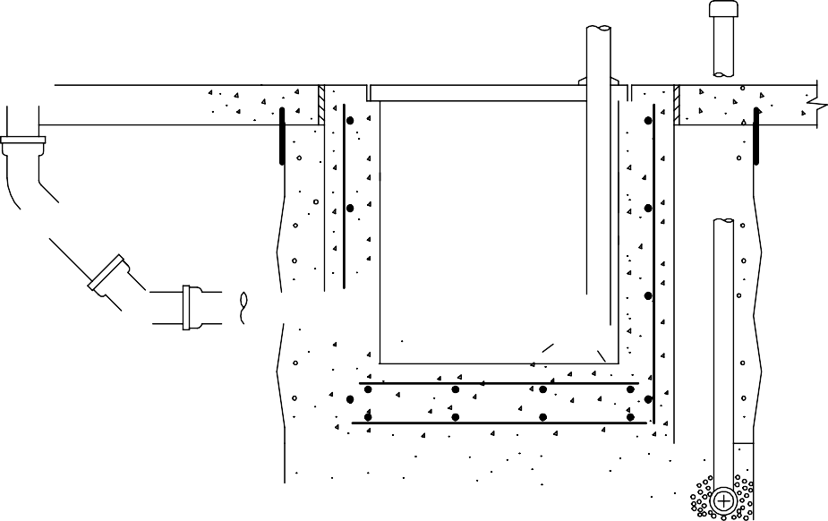
EP 4-8-1 Or
EP 4-8-3
Plate Cover
Double-Walled Piping To Catch Basin
"Double-Walled" External Containment Catch Basin Per Figure 9A Of This
Practice
NOTES:
- See Figures 1 through Figure 7 for double-walled piping component designs.
- (*)Location of sumps and inverts shall be specified in the engineering design.
FIGURE 14A
POLYMER/ CONCRETE PIPE TRENCH
Solid Cover
Seal Finished Grade
2D or 12 in. (min.)
As Needed
(*)Owner's Engineer Approved Polymer- Concrete Trough
8 In. Min.
4 In. Min. Concrete
4 In. (Min.) Conc.
Compacted Subgrade
Section
6 To 20 In. Nom. Pipe Diameter
NOTES:
- (*)Pipe shall be anchored and or thrust-blocked inside trough as specified in the engineering design.
- (*)The need for trench drainage shall be specified by the Owner's Engineer. See Figure 14B if providing trench drainage.
FIGURE 14B TRENCH DRAINAGE (IF PROVIDED)

- Solid Trough Cover
Seal
Trough Into Basin
Grouted
Trough Out Of Basin
Primary Sewer Pipe
Trough Floor
Concrete Trough Bedding
Flexible Joint Filler (Both Sides)
Standard Cast-In Place Catch Basin
Process Sewer Continued
Single Or Double-Walled Segregated Storm Sewer Pipe 90° To Trough
NOTES:
- (*)Owner's Engineer shall specify whether or not to use double-walled piping for segregated storm sewer off of basin.
- Sizing and spacing of catch basins shall be per EP 4-8-1.
- See Figure 8C for cast-in place catch basin design.
FIGURE 15


DOUBLE-WALLED PIPE SEGMENTS RETROFIT
- 2 In. Typ. At Ends
Alignment Rings, See Figure 1B Of This Practice
D
2db b1
b1/2
- Split Design (2 Pieces)
Attach To Adjacent Double Walled Components With Clamped End Connector (Note 3)
Bolt Diameter
(*)Full-Face Gasket - All Bolting Surfaces. Material Shall Be Approved By Owner's Engineer
| Nominal Diameter Primary Pipe (Inches) | db Bolt Diameter (Inches) |
CLTo Bolt CL Spacing (Inches) |
|---|---|---|
| Less Than 10 | 1/2 | 2 |
| 10 To 18 | 5/8 | 2 1/2 |
| Greater Than 18 | 3/4 | 3 |
NOTES:
- See Figure 1A for double-walled pipe design details.
- See Figure 1D for leak detection details.
- See Figure 21 for clamped end connectors.
FIGURE 16
DOUBLE-WALLED SHORT RUNS AND OFFSETS RETROFIT
- See Figure 15 Of This Practice For Bolt Dia.
And Spacing
Bolt Dia. Plus 1/16 In.
Eccentric Reducer (2)
2 In. Typ.
(4 Places)
D
Dc2
b1/2
2db Min. b1
- Attach To Adjacent Double Walled Components With Clamped End Connector
(Note 4)
Offset Runs Split Design (2 Pieces)
Alignment Rings, See Figure 1B Of This
(*)Full-Face Gasket - All Bolting Surfaces. Material Shall Be Approved By Owner's Engineer
NOTES:
- See Figure 2 for double walled offset design details.
- For Dc2 required greater than four times D, see Figure 16. See also Figure 16 for split design.
- Use similar oversize pipe for short runs with reducers.
- See Figure 21 for clamped end connectors.
- For short run with reducer, blind with offset secondary pipe shall be replaced by welding neck or reducing flange, as appropriate.
- See Figure 1D for leak detection details.
FIGURE 17
DOUBLE-WALLED REDUCERS RETROFIT
- 2db (Min.)


b1
b1/2
- 2 In. Typ.
(4 Places)
Bolt Dia. Plus 1/16 In.
See Figure 15 Of This Practice For Bolt Dia.
And Spacing
D
Alignment Rings, See Figure 1B Of This Practice
b1/2
- Attach To Adjacent Double Walled Components With Clamped End Connector (Note 5)
(*)Full-Face Gasket - All Bolting Surfaces. Material Shall Be Approved By Owner's Engineer
Split Design (2 Pieces)
NOTES:
- See Figure 3 for double walled reducer design details.
- See Figure 1D for leak detection details.
- See ANSI/ASME B16.9 and ANSI/AWWA A21.10/C110 and A21.11/C111 for typical lengths of standard reducers.
- If reducer is part of a short run, where the length of the run is less than 10 times the primary pipe diameter, the detail in Figure 16 shall be used.
- See Figure 21 for clamped end connectors.
FIGURE 18 DOUBLE-WALLED ELBOWS
RETROFIT


- (*)Full-Face Gasket - All Bolting Surfaces. Material Shall Be Approved
By Owner's Engineer
2db (Min.)
See Figure 15 Of This Practice For Bolt Dia.
And Spacing
Bolt Dia. Plus 1/16 In.
D
Alignment Rings, See Figure 1B Of This
Practice
2 In. Typ.
(4 Places)
b2/2
- Attach To Adjacent Double
Walled Components With
3db
Min.
b2
- Clamped End Connector
(Note 3)
Mitered Elbow Split Design (2 Pieces)
NOTES:
- See Figure 4 for double walled mitered elbow design details
- Use two segment miter on 45 degree elbow.
- See Figure 21 for clamped end connectors.
- Bolts shall be in accordance with EP 4-5-1.
FIGURE 19 DOUBLE-WALLED WYES
RETROFIT
- 2 Bolts (Min.)
2 In. Typ.


(6 Places)
See Figure 15 Of This Practice For Bolt Dia.
And Spacing
Bolt Dia. Plus 1/16 In.
(*)Full-Face Gasket - All
Alignment Rings,
Bolting Surfaces. Material Shall Be Approved By Owner's Engineer
See Figure 1B Of This Practice
b1/2
- 2db Min.
Attach To Adjacent Double b1
Walled Components With Clamped End Connector
(Note 4)
D
- Split Design (2 Pieces)
NOTES:
- See Figure 6 for double walled wye design details.
- See Figure 1D for leak detection details.
- See ANSI 21.11/AWWA C111 for dimensions of standard wyes.
- See Figure 21 for clamped end connectors
3. Bolts shall be in accordance with EP 4-5-1.
FIGURE 20
DOUBLE-WALLED PIPE TEES RETROFIT
- 2db Min.
b1
b1/2
2db Min. b2
b2/2
- Bolt Dia. Plus 1/16 In.
Attach To Adjacent Double Walled Components With Clamped End Connector (Note 3)
2 In. Typ.
(6 Places)
Alignment Rings, See Figure 1B Of This Practice
See Figure 15 Of This Practice For Bolt Dia.
And Spacing
D
Split Design (2 Pieces)
(*)Full-Face Gasket - All Bolting Surfaces. Material Shall Be Approved By Owner's
Engineer
NOTES:
- See Figure 7 for double walled tee design details.
- See Figure 1D for leak detection details.
- See Figure 21 for clamped end connectors.
- See ANSI/ASME B16.9 and ANSI/AWWA A21.53/C153 for dimensions of standard tees.
4. Bolts shall be in accordance with EP 4-5-1.
FIGURE 21 CLAMPED END CONNECTORS RETROFIT


4 In. Typ.


Primary Pipe
Secondary Pipe
(Split)
Split/Clamped Rubber Sleeve
Final Nom. Dia. = OD Containment + 1/4 IN. 3 In. Long (Min.), 1/8 In. Thick (Min.)
NOTES:
- Rubber shall be compatible with all expected fluid services.
- (*)Sleeve shall be seamed in the field in a manner approved by the Owner's Engineer prior to clamping.
- Clamps shall be adjustable stainless steel straps with a minimum width of 1/2 inch and minimum thickness of 1/16 inch.
© 2026 Inflection Point Engineering, LLC. All rights reserved. The content of this page — including calculation methods, reference data, written analysis, interactive tools, and source code — is the intellectual property of Inflection Point Engineering, LLC and is protected under applicable copyright, trademark, and trade secret laws. Unauthorized reproduction, redistribution, modification, or derivative use in whole or in part is prohibited without prior written consent.
Disclaimer. This material is provided for informational and educational purposes only and does not constitute professional engineering advice. Calculations, reference data, and methodologies are based on published standards and accepted engineering practice but are not a substitute for engineering judgment, site-specific analysis, or review by a licensed Professional Engineer. Inflection Point Engineering, LLC makes no warranties, express or implied, regarding the accuracy, completeness, or fitness for a particular purpose of any content presented here, and shall not be liable for any direct, indirect, incidental, or consequential damages arising from its use. Users assume all risk associated with applying this content to real-world design, operations, or decisions.
© 2026 Inflection Point Engineering, LLC. All rights reserved.