 Section 4 — Structures and Foundations
Sewer Systems
IPE Engineering Practice IPE-EP-4-8-1
Document number: IPE-EP-4-8-1 · Section: 4 — Structures and Foundations
SCOPE
- (*)This Practice covers general design requirements for new waste disposal drainage systems and new stormwater sewers. Where new sewer systems are being designed to tie-in with existing sewer systems, it may be impractical to comply with all the requirements of this Practice. In such cases, new portions of the sewer remote from and unaffected by the tie-in shall comply with this Practice. New and existing portions of the sewer adjacent to and/or affected by the tie-in shall be designed to as great an extent as practical to comply with this Practice. Where requirements of this Practice cannot be practically met, alternative designs shall be developed using sound engineering judgement. The Owner's Engineer shall review and approve all such exceptions.
- The design of piped open sewer systems and open drainage ditches is covered.
- Provisions for control of the spread of fires in the system as well as for limiting volatile emissions are included.
- Drainage of construction sites is not covered here.
- The design of special sewer systems is covered in EP 4-8-3.
- Any deviation from this Practice must be approved by the procedure described in EP 1-1-3.
- An asterisk (*) indicates that a decision or approval by the Owner or the Owner's Engineer is required, or that additional information is furnished by the Purchaser.
- A revision bar indicates all changes made to this Revision.
- Documentation required for sewer construction in accordance with this Practice is given in Table 7.
2.0 REFERENCES
The latest edition of the following standards and publications are referred to herein.
STANDARDS AND PUBLICATIONS
| IPE Engineering Practices |
|---|
| EP 1-1-3 Deviations to IPE Engineering Practices EP 3-5-2 Firewater Systems EP 4-4-1 Roadways and Paving EP 4-8-3 Special Sewer Systems EP 5-1-3 Piping Stress Analysis and Supports |
| Publications |
| International Association of Plumbing and Mechanical Officials. Uniform Plumbing Code. American Petroleum Institute, Manual on Disposal of Refinery Wastes |
STANDARDS AND PUBLICATIONS (CONT.)
| Publications (cont.) |
|---|
| Building Officials and Code Administrators International, Incorporated. The BOCA Basic/National Plumbing Code 40 CFR Part 261, Code of Federal Regulations - Identifications and Listings of Hazardous Waste 40 CFR Part 60, Standards of Performance for New Stationary Sources; VOC Emissions from Petroleum Refinery Wastewater Systems 40 CFR Part 61, National Emission Standards for Hazardous Air Pollutants; Benzene Emissions from Chemical Manufacturing Process Vents, Industrial Solvent Use, Benzene Waste Operations, Benzene Transfer Operations, and Gasoline Marketing System |
| AASHTO Standard |
| M245 Standard Specification for Corrugated Steel Pipe, Polymer PreCoated Sewer and Drains |
| ASTM Standards |
| A53 Specification for Pipe, Steel, Black and Hot-Dipped, Zinc Coated Welded and Seamless A74 Specification for Cast Iron Soil Pipe and Fittings A106 Specification for Seamless Carbon Steel Pipe for High Temperature Service A760 Standard Specification for Corrugated Steel Pipe, Metallic Coated for Sewers and Drains A798 Practice for Installing Factory-Made Corrugated Steel Pipe for Sewers and Other Applications A862 Practice for Application of Bituminous (Asphalt) Coatings for Corrugated Steel Sewer and Drainage Pipe A865 Specification for Threaded Couplings, Steel, Black, and Hot-Dipped, Zinc Coated (Galvanized) C12 Practice for Installing Vitrified Clay Pipe Lines C76 Specification for Reinforced Concrete Culvert, Storm Drain, and Sewer Pipe C425 Compression Joints for Vitrified Clay Pipe and Fittings C443 Specification for Joints for Circular Concrete Sewer and Culvert Pipe, Using Rubber Gaskets C564 Specification for Rubber Gaskets for Cast Iron Soil Pipe and Fittings C700 Vitrified Clay Pipe, Extra Strength, Standard Strength, and Perforated D1557 Test Methods of Moisture-Density Relations of Soils and Soil-Aggregate Mixture Using 10-16 Hammer and 18-in Drop D1785 Poly (Vinyl Chloride)(PVC) Pipe, Schedules 40, 80, and 120. D2321 Recommended Practice for Underground Installation of Flexible Thermoplastic Sewer Pipe |
STANDARDS AND PUBLICATIONS (CONT.)
| ASTM Standards (Continued) |
|---|
| D2665 Poly (Vinyl Chloride)(PVC) Plastic Drain, Waste and Vent Pipe and Fittings D2774 (1983) Recommended Practice for Underground Installation of Thermoplastic Plastic Piping D2949 3.25-Inch Outside Diameter Poly (Vinyl Chloride)(PVC) Plastic Drain, Waste and Vent Pipe and Fittings D2996 Specification for Filament Wound Fiberglass (Glass-Fiber-Reinforced Thermosetting Resin)Pipe D2997 Specification for Centrifugally Cast Reinforced Thermosetting Resin Pipe D4160 Specification for Reinforced Thermosetting Resin Pipe (RTRP) Fittings for Non-Pressure Applications D4161 Specification for "Fiberglass" Glass-Fiber-Reinforced Thermosetting Resin Pipe Joints Using Flexible Elastomeric Seals D4253 Maximum Index Density of Soils Using a Vibratory Table D4254 Maximum Index Density of Soils and Calculation of Relative Density F645 Selection Design and Installation of Thermoplastic Water Pressure Piping Systems F1176 Practice for Design and Installation of Thermoplastic Irrigation Systems with Maximum Working Pressure of 63 psi |
| AWWA Standard |
| M9 Concrete Pressure Pipe |
| ANSI/ASTM Standards |
| C425 Specification for Compression Joints for Vitrified Clay Pipe and Fittings C700 Specification for Vitrified Clay Pipe, Extra Strength, Standard Strength, and Perforated |
| ANSI/AWWA Standards |
| C105/A21.5 Polyethylene Encasement for Ductile Iron Piping for Water and Other Liquids C110/A21.10-82 Ductile Iron and Gray Iron Fittings 3 in. through 48 in., for Water and Other Liquids C111/A21.11-80 Rubber Gasket Joints for Ductile-Iron and Gray-Iron and Pressure Pipe and Fittings C151/A21.51-81 Ductile Iron Pipe, Centrifugally Cast in Metal Molds or Sand-Lined Molds, for Water or Other Liquids C600-82 Installation of Ductile-Iron Water Mains and their Appurtenances |
| API Publication |
| RP 1102 Recommended Practice for Liquid Petroleum Pipelines Crossing Railroads and Highways |
3.0
3.1
3.2
3.3
3.4
3.5
3.6
3.7
3.8
3.9
3.10
3.11
3.12
4.0
4.1
4.2
DEFINITIONS
Catch basin - An open basin that collects stormwater runoff from Plant surfaces and Plant wastewater from process drains.
Contractor - Company or business that agrees to furnish materials or perform specified services at a specified price and/or rate to the Owner.
Fire seal - means of preventing the movement of a flame front in the vapor space of a partially filled pipeline, also referred to as water seal or fire stop.
Junction Box - A manhole or other access to a wastewater sewer line system.
Manhole - Cased hole that allows bodily access to a sewer system through a covered hatch on top.
Manufacturer - The recipient of a direct or indirect purchase order for materials and/or equipment. In this context, a direct order is one issued to a manufacturer by a contractor or the Owner. An indirect order is one issued to a manufacturer by a vendor (recipient of a direct order) for materials, fabricated components, or subassemblies.
Non-hazardous - Not meeting the definition of hazardous waste as defined in 40 CFR Part 261. OSBL - Outside battery limits.
Owner - Inflection Point Engineering, LLC.
Owner's Engineer - A Inflection Point Engineering, LLC appointed engineer.
Time of Concentration - time required for stormwater to flow from the most remote point (in time of flow) of the drainage area to the outlet.
VOC - Volatile organic compounds (e.g., toluene).
GENERAL
Plant wastewater collection systems shall be designed in accordance with the principles and practices outlined in the API Manual on Disposal of Plant Wastes. All systems shall be in accordance with local codes and regulations. The project specifications shall be referred to for scope of sewer systems, design details, and equipment descriptions. Items to be considered in the design include segregation of plant wastes, oil recovery, sludge disposal, chemical wastes, ballast water from tankers and barges, spent clays and other liquid wastes.
Plant waste disposal systems shall include all, or combinations, of the following sewer systems:
- Oil-free water sewer (waste and storm water).
- Contaminated water sewers (storm water, cooling water).
- Process water sewer.
- Sanitary sewer.
- Special sewers (ballast water, chemical wastes, pressure sewers).
4.3 (*)Design of plant drainage and sewer systems shall be subject to Owner's Engineer approval.
PIPE AND DITCH SIZE
- General Requirements
- Sewers shall be sized to flow at 70 percent of their capacity at the design flow rate. Sewer systems shall be designed to drain completely (except for seals) at no flow.
- Minimum line size for any single branch shall be 4 inches. Minimum size for any main containing flow of two or more single lines shall be 6 inches.
- Maximum flow velocity shall be 7 feet per second. Flow velocities of 3 to 4 feet per second at average flow are preferred.
- Minimum velocities for line flow at design rate are shown in Table 3.
- Velocity and depth of flow shall be calculated using the Manning Equation with the values shown in Table 4 for the roughness coefficient, "n".
- The minimum slope of ditches shall be 0.005 feet per foot.
- (*)Sidewalls of unlined earthen ditches shall have slopes no steeper than 1.5 horizontal to 1.0 vertical, nor steeper than the angle of repose of the earth when wet. Requirements for sidewall surface treatment or other special features shall be subject to Owner's Engineer approval if not specified in project specifications.
- Design Flows
- Rainfall
- The design rainfall shall be based on U.S. Weather Bureau records or on the intensity/frequency curves for the locality. This data shall form part of the project specification. The return period shall be at least 10 years, but may be longer depending on the degree or seriousness of flooding.
- The Rational Formula shall be used to determine maximum flow rate for rainwater flow conditions. Design shall be based on the rainfall intensity for the design return period and for a duration equal to the time of concentration. The Rational Formula is as follows (refer to Table 5:
Where:Q ClA
Q acres inches per hour (approx. cu. ft. per second)
A drainage area in acres
l Rainfall intensity in inches per hour C runoff coefficient
- Firewater: The volume of firewater for each process unit drainage system shall take into account the fixed water spray system and fixed monitor protection. The total design volume shall be based on the table given in EP 3-5-2. The design firewater flow rate from each drainage area to a catch basin shall be 500 gallons per minute.
- Applicable Flows
- Process Water Sewer
- If separate storm sewers are not provided, process water sewers shall be sized based on maximum flow from process drainage plus rainfall or maximum flow from process drainage plus firewater design, whichever is greater.
- Drainage from hydrostatic tests of vessels shall not be included when determining design capacity of process water sewers, except in cases where large vessels may be drained.
- Drains serving large vessels shall be sized to prevent the overflow of inlets in the area surrounding the vessel.
- Storm sewers shall be sized either for rainfall or firewater drainage, whichever is larger.
- Sanitary sewers shall be sized based on the fixture unit values listed in the applicable plumbing code. If the new sewer is downstream of an existing sewer, sufficient allowance shall be made for infiltration and inflow.
- Drainage ditches may be used to collect storm water and firewater OSBL. Only non-oily, non- hazardous water is allowed in ditches.
SURFACE DRAINAGE
- Drainage Area Layout
- Drainage areas shall be arranged to prevent the spread of fire from one area to another. The slope of paving or grade shall be arranged to drain water away from process equipment, vessels furnaces, and from under pipe racks, see EP 4-4-1 for pavement design.
- Drainage from various areas shall flow separately to catch basins or manholes with fire seals before joining the closed sewer system.
- For process units, the drainage area shall be a maximum of 3000 square feet for one catch basin. The paving of each area shall slope to a catch basin located at the low point, normally 6 inches below high point. The slope shall be between 1/8 inch and 1/2 inch per foot.
- Drains from Diked Areas
- Where provision is made for draining water from diked areas, drainage shall be provided at a uniform slope or not less than 1 percent away from the tank(s) towards a sump or catch basin located at the farthest practical distance from the tank(s).
- The catch basin shall be sealed on the outlet. The pipe shall be valved outside the dike. The discharge may be to a ditch (offsite areas only) or to a closed sewer system. Minimum pipe size is 8 inches.
- OSBL Drainage Ditches
- OSBL drainage ditches shall be located and designed to inhibit the spread of fire. Fire stops shall be provided at about 700-foot intervals and at road intersections in tank field areas. A suitably sealed closed conduit under a road or rail crossing shall be used for this purpose. Each fire stop shall consisting of a closed drain section at least 30 feet long with a fire seal at the upper end accessible for cleaning.
- Drainage ditches shall be separated from pipe racks by a horizontal distance of at least 10 feet from the outermost pipe or structural member, and from process equipment by at least 30 feet. Where pipes cross ditches, pipe flanges and other mechanical-type joints shall be avoided. Overhead and above grade hydrocarbon and firewater lines crossing over open ditches shall be of welded construction. They shall be protected from fire by a culvert under the pipe crossing or by fireproofing the pipe with insulation.
PROCESS DRAINS
- Each and every drain opening to the atmosphere that is a potential source for VOC emission shall be equipped with a water seal or a tightly sealed cap or plug.
- For equipment drains, sewer connections with open bells or hubs at least 6 inches in diameter shall normally project 2 inches above pavement and 6 inches above soil or gravel grades.
- (*)Each pump shall be provided with a drain bell. Unless otherwise specified by the Owner's Engineer, drain lines from up to 4 pumps may be joined before entering a sealed catch basin or manhole.
- Drains from elevated equipment shall be provided with open breaks consisting of a funnel or hub visible from the drain valve handwheel and shall be sealed in catch basins at grade.
- Floor drains in buildings that house pumps or compressors, or in shop areas, shall be used only for wastewater and shall be equipped with bell seals and strainer plates.
- (*)Drainage areas around heaters shall be arranged to provide dry catch basins adjacent to, but not under, the heater. For conventional horizontal heaters, four dry boxes shall be provided. For smaller vertical heaters, two dry boxes may be provided. The arrangement of dry boxes and the number installed at heaters shall be subject to Owner's Engineer approval. The lines from dry catch basins shall be individually sealed at a catch basin or manhole at least 30 feet from the heater.
8.0 CONTROL ROOMS AND SWITCH ROOMS
No drains shall be installed in control rooms within control houses, electric substations or switch rooms. Drain connections for the remainder of a control house shall be restricted to sanitary systems.
APPURTENANCES
- Catch Basins
- (*)Catch basins shall be adequately sized to cope with the full catchment design condition specified in this Practice for stormwater and firewater. The minimum outlet pipe size shall be 6 inches. Fire seals shall be provided on all inlet lines to any catch basin that may contain flammable liquids or VOC, including benzene. Removable gratings shall be provided. These gratings shall be designed to carry loads of at least 60 pounds per square foot, or as specified in the project specifications.
- (*)In process units, no more than five catch basins shall be arranged to flow in series before discharging into a manhole, unless otherwise specified by the Owner's Engineer. Grating- covered catch basins shall not be located beneath process equipment or pipeways. They shall be spaced at least 2-1/2 feet horizontally from pumps and 5 feet horizontally from compressors and uninsulated vessels containing hydrocarbons.
- Manholes
- (*)Unless otherwise specified by the Owner's Engineer, manholes shall be provided as follows:
- Immediately outside of process unit areas
- Where sewer mains (8 inches and larger) change direction more than 15°
- Where laterals connect to a sewer main
- Where size changes
- Where there are abrupt changes in elevation
- For cleaning and inspection in long straight runs.
- (*)Manholes shall be spaced no more than 300 feet apart for sewers up to 20 inches in size, and no more than 500 feet apart for sewers 24 inches and larger. Fire seals shall be provided on all inlet lines to any manhole that may contain flammable fluids, except main truck lines. Manholes shall be sealed and vented to a safe location in accordance with paragraph 9.5 of this Practice. Removable solid manhole covers are required and shall be designed to carry traffic loads as specified in the project specifications. Manhole covers shall be set at grade in paved areas and six inches above grade in unpaved areas.
- Fire Seals
(*)Fire seals shall be individually installed on each drain to prevent spread of fire and release of VOC in process and storm sewer systems, see Figure 1. The preferred method for sealing drain lines is to seal on the inlet to the downstream catch basin or manhole. This method permits displacement of accumulated oil into the sewer system. The Owner's Engineer must approve the use of seals on the catch basin outlet. In either case, the seal shall provide a minimum of a 6-inch submergence below the liquid level. A removable plug shall be provided to allow cleaning of the seal pipe. P or U traps shall not be used in underground drainage lines, unless approved by the Owner's Engineer. Seals shall also be provided in lines draining diked tank areas and where ditches tie into a closed sewer system.
- Cleanouts
Requirements for cleanouts are as follows:
- Cleanouts shall be provided where the sewer turns 90°. Cleanouts shall also be provided when the sewer turns 45° and is preceded by a straight run of 50 feet or more.
- Cleanouts shall be installed to facilitate cleaning in direction of flow.
- Drain hubs of bells may be considered as cleanouts if the run to the drain header is less than 20 feet and total turns do not exceed 135°. This includes the 90° turn from vertical to horizontal.
- In the absence of a manhole or catch basin, a cleanout shall be provided in every 200 feet of straight sewer run in lines 12 inches and smaller.
- Cleanouts shall be equal to the line size in sanitary sewers and 4 inches minimum in all other sewers.
- Vents
- (*)Where flammable vapors or VOC may be present, manholes, junction boxes, and barometric condenser sumps shall be provided with sealed covers and shall be vented to a safe location. The vent line shall not be between NPS 2 and NPS 4. Unless otherwise specified by the Owner's Engineer, vents for flammable vapors shall terminate:
- At least 8 feet above any adjacent service platform.
- A minimum of 20 feet above grade.
- At least 50 feet measured horizontally from any fired heater or other source of ignition.
- For nonflammable vapors, the vent pipe shall be at least 3 feet in length.
- (*)The vent line shall be oriented to avoid hazards to personnel. When required by regulations or when specified by the Owner's Engineer, a flow indicator shall be installed on each vent pipe to ensure that organic vapors are not continuously vented to the atmosphere during normal operation.
- In lieu of venting manholes, junction boxes, and barometric condenser sumps to atmosphere, the vent may be connected to a closed-vent system which leads to a control device.
- The closed-vent system shall:
- Be designed to operate with no detectable emissions as indicated by an instrument reading of less than 500 ppmv VOC above background.
- Have a flow indicator installed on each vent stream to the control device to ensure that the vapors are being routed to the device. The flow indicator shall be installed in the vent stream at the nearest feasible point to the control device inlet but before being combined with other vent streams.
- Have gauging and sampling devices that are gas-tight, except when gauging or sampling is taking place.
- The control device shall be designed in accordance with the following conditions:
- An enclosed combustion device (e.g., vapor incinerator, boiler, or process heater) shall meet one of the following conditions:
- Reduce the organic emissions vented to it by 95 weight percent or greater.
- Achieve a total organic compound concentration of 20 ppmv on a dry basis corrected to a 3 percent oxygen: or
- Provide a minimum residence time of 0.5 seconds at a minimum temperature of 760°C. If a boiler or process heater is used as the control device, then the vent stream shall be introduced into the flame zone of the boiler or process heater.
- A vapor recovery system (e.g., carbon absorption system or condenser) shall recover the organic emissions vented to it with an efficiency of 95 weight percent or greater.
- Flare for wastewater systems shall comply with the requirements of IPE's Environmental Guidelines and those of 40 CFR 60.18.
MATERIAL
- Materials shall be selected in consideration of temperature, internal and external corrosion, loading, pipe size, cost, installation requirements, and availability of pipe.
- Inside surfaces of pipe, including compression gaskets, shall be fully resistant to corrosion caused by characteristics of the wastewater. External surfaces shall be coated or enclosed to protect against corrosion caused by the soil, backfill, and/or groundwater.
- Acceptable types of pipe for various services are given in Table 1. Applicable standards are given in Table 2.
- (*)Joints of underground pipe shall be of the compression gasket type or welded construction, if approved by the Owner's Engineer.
- Joints of above ground pipe shall be welded, mechanically jointed, or flanged.
INSTALLATION
- General
- Piping, ditches, and other components of sewer systems shall be installed in accordance with design drawings and specifications.
- Pipe trenches shall be excavated as shown on the drawings or as called for in this Practice. Sides of trenches shall be properly sheathed and braced. Trench walls shall be vertical from the bottom of the excavation to the top of pipe elevation. The trench shall be wide enough to provide a free running space on each side of the pipe.
- Whenever wet unstable soil that is not capable of properly supporting the pipe is encountered in the trench bottom, it shall be removed and the trench backfilled to the bottom grade with gravel, cement stabilized sand, or concrete. Where the trench bottom is located in rock, the trench shall be over-excavated and backfilled with a minimum of 4 inches of clean sand.
- Excavation for manholes and other appurtenances shall be sufficient to permit the construction required. Where manholes are to be plastered, a clear space of at least 6 inches shall be provided around the manholes. Excavation for manholes and other structures shall not be below the depth specified.
- Pipe beds shall be smooth, even, and free of elements that may damage the pipe or the pipe's protective coating. Bell holes shall be excavated so that, after placement, only the barrel of the pipe receives bearing pressure from the trench bottom. When more than one sewer pipe is laid in a common trench, the tops of pipe shall be at the same elevation.
- (*)The pipe shall be laid true to the line and grade as shown on the drawings. Pipe shall be laid, assembled and joined in accordance with the manufacturer's installation handbook, using the required gaskets, tools, and lubricants. Coatings shall be protected from damage. Coatings that arrive on site damaged may be repaired at the discretion of the Owner's Engineer.
- Bell and spigot gravity pipe shall be laid with spigot ends pointing in the direction of flow. The trenches shall be kept free of water until the pipe has been tested and backfilled. As the work progresses, the interior of the pipe shall be cleaned of all and superfluous materials.
- At the suspension of work each day, all openings along the line shall be securely closed with suitable stoppers to prevent earth or other substances from entering the pipe. Any pipe that has been disturbed after being laid, shall be taken up, the joints cleaned and the pipe properly re- laid.
- (*)All material used for trench backfill shall be acceptable to and approved by Owner's Engineer before placement. The material shall be clean sand, sand and gravel, or approved on-site material. All backfill material shall be free of boulders, rocks, and other large-sized hard material. Backfill around manholes shall be carefully placed and thoroughly compacted to 70% relative density per ASTM D4253 and ASTM D4254 for cohesionless soils, and 90% of maximum dry density determined in accordance with ASTM D1557 for cohesive soils.
- If crushed limestone is approved, metallic piping shall be coated and wrapped to prevent corrosion.
- The backfill from the bottom of the trench or top of the sand cushion, to 12 inches above the top of the pipe, shall be deposited in the trench on both sides of the pipe in 6 inches loose layers and hand compacted to the requirements of this Practice.
- (*)Remaining backfill may be compacted in the most economical method to obtain the required compaction. Flooding or ponding shall not be permitted as a method of backfill compaction. All methods of compaction shall be approved by Owner's Engineer before starting operation.
- Pressurized underground lines with mechanical joints shall be restrained from movement by thrust blocking, when required. Thrust blocks are required where the pipe changes direction, reduces in size, ends, or is valved. The block shall be formed against undisturbed earth that has been prepared by hand. Thrust blocks shall be sized per ASTM F1176 and EP 5-1-3.
- Crossings
- Crossings of railroads and highways shall be in accordance with API 1102.
- Under roadways and vehicle-traveled areas, sewer lines requiring protection shall be encased in a concrete envelope or in a sleeve providing a 3-inch minimum total clearance. Alternatively, they shall be covered with a load-bearing plate or concrete slab.
- Sanitary
- Sanitary piping shall be designed and installed in accordance with the latest edition of the Uniform Plumbing Code, or the BOCA Basic National Plumbing Code, or as required by any local codes and ordinances. In the case of conflicts, the most stringent requirements shall apply.
- Installation of sanitary sewers in proximity to potable water lines shall conform to local codes and ordinances. In general, potable water lines shall be at a higher elevation than sanitary sewers in close proximity.
- Pipe Systems
Piping shall be installed in accordance with Figure 2 and Table 6.
TESTING
- (*)The Contractor shall perform hydrostatic, leakage and operational tests as specified herein. The Contractor shall perform all excavation and other work required to locate and repair leaks and correct other defects which may be disclosed or develop under tests. The Contractor shall replace all coating, painting, backfill, or other permanent work removed in locating or repairing leaks and in correcting defective piping. Results of all testing shall be submitted to the Owner's Engineer.
- The interior of all lines to be tested shall be thoroughly cleaned before starting the testing procedure.
- No underground sewer system requiring tested shall be backfilled, covered, concealed or put into service until the test has been complete, and the system inspected and approved. Pressure systems shall be backfilled over the pipe lengths except at the joints, to a point two feet above the top of the pipe to prevent movement under test pressure. All joints shall remain uncovered for inspection until the pressure line has been tested and approved.
- Pipe having free surface flow, with the exception of segregated storm sewers, shall be given a water exfiltration test.
- For mechanically-joined systems, the test shall be conducted between successive manholes by closing the lower end of the pipe to be tested and the inlet pipe of the upper manhole with stoppers. The pipe and manhole shall be filled with water to a point at least 4 feet above the invert of the pipe at the center of the upper manhole if the pipe's outside diameter is less than 48 inches. Otherwise, the system shall be fitted to the top of the manhole; or if ground water is present, 4 feet above the average adjacent ground water level. The pipe shall be thoroughly wetted prior to the start of the test. Duration of testing shall be determined based upon field conditions, but shall be at least 30 minutes.
- For welded systems, a hydrotest shall be performed in accordance with EP 5-5-3.The test pressure shall be 25 psig. Alternatively, tests at higher pressures can be performed if the test plan is first submitted to the Owner's Engineer for approval.
- The allowable leakage shall be computed by the formula:
£ 0.00002LDH 0.5
Where :
£ allowable leakage, gpm L length of pipe tested, feet D lD of the pipe, inches
H difference in elevation, in feet, between the water surface in the upper manhole and the invert of the pipe at the lower manhole; or if ground water is present above the invert of the pipe in the lower manhole, the difference in elevation between the water surface in the upper manhole and the groundwater at the lower manhole.
- Pressure Pipe
- Force mains and other pressure piping which have bell and spigot gasketed joints shall be given a pressure and leakage test as specified in AWWA C600.
- Prior to testing reinforced concrete pipe, the section of the pipeline to be tested shall be filled with water and placed under a slight pressure for at least 48 hours. The pipeline shall then be brought up to the test pressure, and that pressure shall be maintained on the section under test for a period of not less than 4 hours.
- Fiberglass reinforced pipe, cast iron, ductile iron and other pipe material, with solvent welded, welded, threaded, flanged, grooved end, mechanical joint or flexible couplings shall be pressure tested as specified in AWWA C600. No leakage shall be permitted.
- No special pressure or leakage testing is required for gravity storm drainage pipe. Leakage shall be minimized by installation in a workmanlike manner in accordance with the manufacturer's recommendations.
FLUSHING
- All piping shall be flushed clean of all dirt and foreign material following completion of the hydrostatic test.
- (*)The Contractor shall provide all equipment, and supplies for performing the work, and shall waste the water at locations or by procedures approved by the Owner. The Contractor shall be responsible for furnishing fittings and all special pipe taps required for testing and flushing.
14.0 TABLES
TABLE 1
PIPE SELECTION GUIDE
| Service | Service | Type of Pipe |
|---|---|---|
| Process wastewater | Carbon steel pipe | |
| Process wastewater | Non-corrosive | Cast iron soil pipe |
| Process wastewater | Non-corrosive | Ductile iron pipe |
| Process wastewater | Non-corrosive | Reinforced concrete pipe |
| Process wastewater | Corrosive | Vitrified clay pipe |
| Process wastewater | Corrosive | Haveg® pipe |
| Process wastewater | Corrosive | Any of the pipes listed for non-corrosive service if suitably lined |
| Process wastewater | Corrosive | Lined fiberglass reinforced plastic |
| Stormwater sewer | Reinforced concrete pipe | |
| Stormwater sewer | Cast iron soil pipe | |
| Stormwater sewer | Ductile iron pipe | |
| Sanitary sewer | PVC pipe | |
| Sanitary sewer | Non-corrosive Gravity | Cast iron soil pipe |
| Sanitary sewer | Non-corrosive Gravity | Reinforced concrete pipe |
| Sanitary sewer | Force main | Ductile iron pipe |
| Sanitary sewer | Corrosive (labs) | Mechanical joint, flame retardant, polypropylene |
| Sanitary sewer | Corrosive (labs) | Lined fiberglass reinforced pipe |
| Floor drain | Floor drain | Cast iron soil pipe |
| Floor drain | Floor drain | Ductile iron pipe |
| Culvert | Culvert | Corrugated metal pipe with bituminous or polymer coating |
| Culvert | Culvert | Reinforced concrete pipe |
| Vent piping | Vent piping | Galvanized steel SCH 40 |
TABLE 2
PIPE MATERIAL STANDARD REFERENCES
| Type of Pipe | Applicable Standards |
|---|---|
| Cast iron soil pipe | ASTM A74 ASTM C564 |
| Ductile iron pipe | ANSI/AWWA C151/A21.51 ANSI/AWWA C110/A21.10 ANSI/AWWA C111/A21.11 ANSI/AWWA C105/A21.5 |
| Reinforced concrete pipe | ASTM C76 ASTM C443 |
| Vitrified clay pipe | ANSI/ASTM C700 ANSI/ASTM C425 |
| Fiberglass reinforced plastic pipe | ASTM D4160 ASTM D4161 ASTM D2996 ASTM D2997 |
| Corrugated metal pipe | ASTM A760 ASTM A862 AASHTO M245 |
| Haveg® | As manufactured by Haveg® a division of Ametek |
| Mechanical joint, flame retardant polypropylene | As manufactured by Enfield Industrial Corp. 650A Anthony Trail Northbrook, IL 60062, or equal |
| Galvanized pipe | ASTM A53- Grade B ASTM A106 ASTM A865 |
| PVC pipe | ASTM D1785 ASTM D2665 ASTM D2949 |
TABLE 3
MINIMUM LINE FLOW VELOCITY
| Condition | Velocity (Feet per Second) |
|---|---|
| General, such as storm, oily water and sanitary sewers | 2.5 |
| Where moderate amounts of sand or other particles are carried, such as from unpaved areas | 3.0 |
| Where heavy amounts of sand or other particles may be anticipated |
4.0 |
TABLE 4 ROUGHNESS COEFFICIENT
| Item | Roughness Coefficient, n |
|---|---|
| cast iron, concrete | 0.013 |
| corrugated steel pipe | 0.021 |
| clay lined ditches | 0.023 |
| gravel lined ditches | 0.030 |
TABLE 5 RUNOFF COEFFICIENT, C
| AREAS | RUNOFF COEFFICIENT, C |
|---|---|
| roofs or concrete paved areas | 0.95 |
| asphalt paved areas | 0.85 |
| gravel areas | 0.70 |
| railroad yards | 0.40 |
| unimproved areas | 0.30 |
TABLE 6
PIPING INSTALLATION STANDARD REFERENCES
| PIPE | STANDARD |
|---|---|
| Cast Iron Soil Pipe | ASTM C12 |
| Vitrified Clay Pipe | ASTM C12 (class B bedding) |
| Ductile Iron Pipe | ANSI/AWWA C600 |
| Concrete Pipe | AWWA Manual M9 |
| PVC, Fiberglass Reinforced Pipe | ASTM D2321 ASTM D2774, ASTM F645 (as applicable) |
| Corrugated Steel Culvert Pipe | ASTM A798 |
NOTE:
For galvanized pipe. All galvanized pipe shall have tapered threads. Threads shall be cut neat with sharp tools. The pipe threads shall be wrapped with Teflon tape, or approved equal, before the pipe is screwed together. After a screwed joint has been tightened, it shall not be backed -off and re-tightened. If it is necessary to back-off or un-tightened a screwed joint, the fitting shall be removed, the threads cleaned and new Teflon tape applied before the joint is made. The exterior of all underground galvanized pipe joints shall be protected with a cold applied primer and wrapping and shall be applied per manufacturer's instruction.
TABLE 7 DOCUMENTATION REQUIREMENTS FOR SEWER SYSTEMS PER EP 4-8-1
| Item | Description | Format | As-Built |
|---|---|---|---|
| 1 | Local rainfall curves forming part of the specifications. | Text | N/A |
| 2 | Sewer systems drawings and specifications. | See EP 2-5-2 | Yes |
| 3 | Results of all testing of sewer systems. | Text | N/A |
15.0 FIGURES
FIGURE 1
TYPICAL EQUIPMENT AND SLAB DRAINAGE ARRANGEMENT
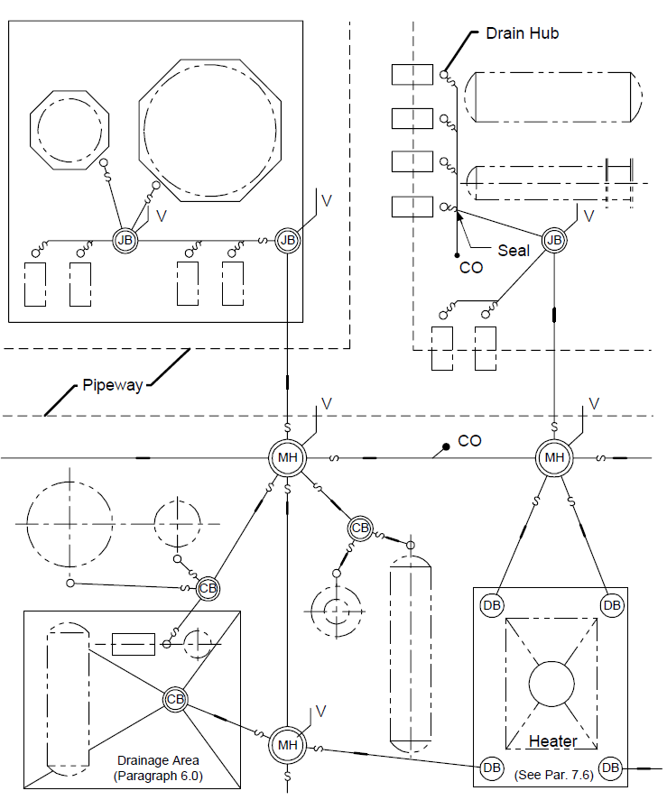
CB - Catch Basin CO - Clean Out DB - Dry Box
JB - Junction Box MH - Manhole
S - Fire or Vapor Seal, as specified V - Vent
FIGURE 2 PIPE TRENCHES (NOTES 3 AND 4)
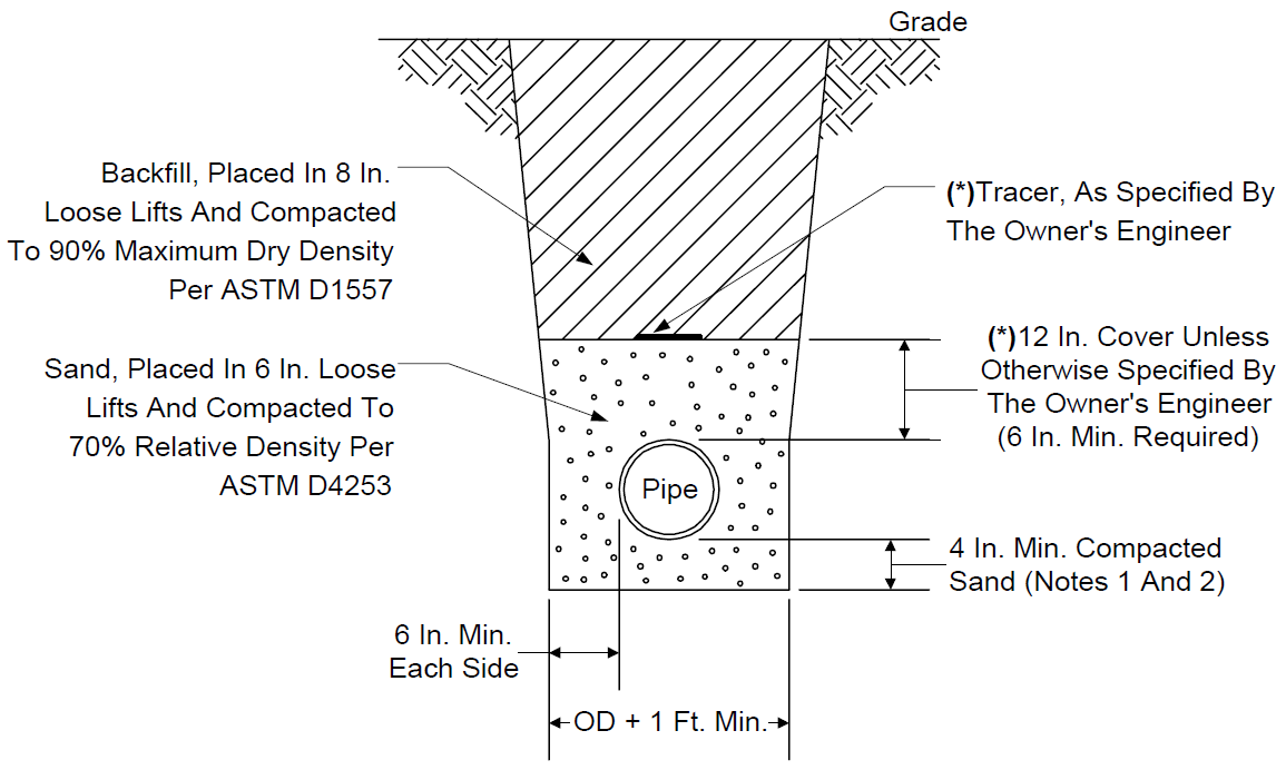
NOTES:
- A foundation may be required beneath the sand bedding to reduce pipe settlement.
- For specific embedment materials, see installation procedures reference in this Practice.
- See ASTM A798 for corrugated pipe trenches.
- See ASTM C12 for vitrified clay pipe trenches.
- (*)Flooding shall not be used unless approved by the Owner's Engineer.
© 2026 Inflection Point Engineering, LLC. All rights reserved. The content of this page — including calculation methods, reference data, written analysis, interactive tools, and source code — is the intellectual property of Inflection Point Engineering, LLC and is protected under applicable copyright, trademark, and trade secret laws. Unauthorized reproduction, redistribution, modification, or derivative use in whole or in part is prohibited without prior written consent.
Disclaimer. This material is provided for informational and educational purposes only and does not constitute professional engineering advice. Calculations, reference data, and methodologies are based on published standards and accepted engineering practice but are not a substitute for engineering judgment, site-specific analysis, or review by a licensed Professional Engineer. Inflection Point Engineering, LLC makes no warranties, express or implied, regarding the accuracy, completeness, or fitness for a particular purpose of any content presented here, and shall not be liable for any direct, indirect, incidental, or consequential damages arising from its use. Users assume all risk associated with applying this content to real-world design, operations, or decisions.
© 2026 Inflection Point Engineering, LLC. All rights reserved.