 Section 4 — Structures and Foundations
Steel Stacks
IPE Engineering Practice IPE-EP-4-7-1
Document number: IPE-EP-4-7-1 · Section: 4 — Structures and Foundations
SCOPE
- This Practice provides mandatory requirements for the structural design and construction of self-supported steel stacks, both lined and unlined, and guidelines for the inspection and maintenance of steel stacks.
- The steel stacks covered by this Practice are further limited to those of circular cross section. The wind load requirements in this Practice are for single stacks, not stacks grouped in pairs or rows, and stacks with well-removed from adjacent structures of comparable height. Stacks located adjacent to other stacks or tall structures are susceptible to larger wind forces than can be appropriately analyzed by the methods given in this Practice.
- Concrete and masonry chimneys are not covered by this Practice.
- Any deviation from this Practice must be approved by the procedure described in EP 1-1-3.
- An asterisk (*) indicates that a decision or approval by the Owner or Owner's Engineer is required or that additional information is furnished by the Purchaser.
- A revision bar indicates all changes made to this Revision.
- Documentation required in accordance with this Practice is given in Table 3.
2.0 REFERENCES
The latest edition of the following standards and publications are referred to herein.
STANDARDS AND PUBLICATIONS
| IPE Engineering Practices |
|---|
| EP 1-1-3 Deviations to IPE Engineering Practices Design EP 4-1-1 Criteria and Loads for Structures EP 4-2-3 Reinforced Concrete Foundations EP 4-5-3 Auxiliary Structures for Operation and Maintenance EP 4-7-1C Steel Stacks Inspection Checklist EP 10-3-1 Shop Painting EP 11-1-1 Internal Insulating and Refractory Lining EP 11-1-2 Fired Heater Refractory EP 11-3-1 Insulation Design EP 11-3-3 Insulation Application - Vessels and Equipment |
| AISI Publication |
| Steel Plate Engineering Data - Volume 2, Part V |
| AISC Specification |
| Specification for the Design, Fabrication and Erection of Structural Steel for Buildings |
STANDARDS AND PUBLICATIONS (CONT.)
| ASCE |
|---|
| 7 Minimum Design Loads for Buildings and Other Structures |
| ASME Codes and Standards |
| Section VIII Pressure Vessels, Division 1 STS-1 Steel Stacks |
| ASTM |
| A6 Rolled Steel Plates, Shapes, Sheet Piling and Bars Used for Structural Use A36 Structural Steel A283 Low and Intermediate Tensile Strength Carbon Steel Plates A285 Pressure Vessel Plates, Carbon Steel, Low- and Intermediate--Tensile Strength A325 High-Strength Bolts for Structural Steel Joints A368 Stainless and Heat-Resisting Steel Wire Strand A516 Pressure Vessel Plates, Carbon Steel, Moderate- and Lower Temperature Service A563 Carbon and Alloy Steel Nuts A573 Structural Carbon Steel Plates of Improved Toughness A603 Zinc-Coated Steel Structural Wire Rope C401 Classification of Castable Refractories F436 Hardened Washers |
| AWS |
| D1.1 Structural Welding Code |
| British Standard |
| BS 4076 Steel Chimneys |
| NFPA Standard |
| 780 Standard for the Installation of Lightning Protection Systems |
| Publications |
| "Dynamic Stability Design of Stacks and Towers," K. DeGhetto, W. Long, A.S.M.E. Transactions, November, 1966. "Flow-Induced Vibrations," R. Blevins, Van Nostrand Reinhold, New York, 1990. "Practical Solutions to Some Wind-Induced Vibration Problems," R.E. Whitbread, National Physics Laboratory (England). "Wind Engineering," H. Liu, Prentice Hall, Englewood Cliffs, New Jersey, 1991. |
DEFINITIONS
- Contractor - Company or business that agrees to furnish materials or perform specified services at a specified price and/or rate to the Owner.
- Erector - Contractor responsible for erection of structural steel.
- Inspector - A Inflection Point Engineering, LLC appointed engineer or inspector.
- Manufacturer - The recipient of a direct or indirect purchase order for materials and/or equipment. In this context, a direct order is one issued to a manufacturer by a contractor or the Owner. An indirect order is one issued to a manufacturer by a vendor (recipient of a direct order) for materials, fabricated components, or subassemblies.
- Owner - Inflection Point Engineering, LLC.
- Owner's Engineer - A Inflection Point Engineering, LLC appointed engineer.
MATERIALS
- (*)Unless otherwise specified by the Owner's Engineer, plate materials shall be ASTM A36, A283, A285, A516 and A573. Structural steel shall be ASTM A36 and structural steel shapes per ASTM A6. Other materials listed in ASME STS-1, and alloy materials shall not be used without the approval of the Owner's Engineer. The Owner's Engineer shall also specify any associated post weld heat requirements.
- (*)Castable refractory, if required, shall be a medium weight insulating type per ASTM C401, with a minimum dry installed density of 75 lbs./cubic feet, unless otherwise specified by the Owner's Engineer. Additional guidance on internal linings is given in ASME STS-1.
- (*)Bolts shall be ASTM A325, nuts shall be ASTM A563, and washers unless otherwise specified by the Owner's Engineer. When required, hardened washers shall be ASTM F436.
- (*)Guy wires and their fittings, if permitted, shall be fabricated from zinc-coated wire rope conforming to ASTM A603, stainless steel wire conforming to ASTM A386. The Owner's Engineer shall approve the use of other wire rope materials.
GENERAL DESIGN
- General
- (*)Stacks shall be designed to be self-supporting, unless a guyed stack is specified and approved by the Owner's Engineer. Special stack designs, including double-walled and derrick-supported stacks, shall be approved by the Owner's Engineer.
- Rules of this Practice shall apply only to isolated stacks having no structure of similar height within a minimum distance of 8 times the stack's outside diameter.
- (*)The Owner's Engineer shall approve methods for analyzing stacks that are closely spaced or near other tall structures.
- Design loads shall be in accordance with EP 4-1-1 and additional requirements of this Practice. Wind and earthquake loads shall not be considered to act concurrently.
- Lining weight and stiffness shall be included in the calculation of dead loads for the operating load case, and in the determination of the structural natural frequencies for wind and seismic load calculations. However, the strength and stiffness of the lining shall be excluded from stress calculations. The erection load case shall consider the unlined stack's mass and stiffness.
- In all wind load calculations, the outside diameter of the stack shall include any external insulation or cladding.
- Painting shall be done in accordance with EP 10-3-1.
- Steel stacks and their associated equipment shall be provided with suitable protection against lightning in accordance with NFPA 780.
- Internal linings shall be in accordance to EP 11-1-1 and additional requirements of this Practice.
- External insulation shall be in accordance with EP 11-3-1 and additional requirements of this Practice.
- (*)All design calculations shall be submitted to the Owner's Engineer for approval.
- (*)Plan, elevation and detail drawings required for the construction of a steel stack shall be submitted to the Owner's Engineer.
- Shell Design
- The design of stack shells is based on the ASME STS-1, the AISI Publication and the British Standard, see Section 2.0.
- Minimum plate thickness shall be the calculated thickness resulting from stress, deflection and ovaling considerations, plus the applicable corrosion allowance, but not less than 1/4 inch nor less than D/500, where D is the outside diameter of the stack at the height under consideration.
- Allowable stresses shall be per Table 1. No increase in allowable stress is permitted when wind and earthquake loads are considered. Allowable stresses for belled or tapered base sections of stacks shall be based on formulas in Table 1 using an equivalent cylindrical radius, R1, see Figure 1.
- The total corrosion allowance shall be the sum of the internal and external corrosion allowances per Table 2.
- Cone to cylinder transitions shall be designed based on an allowable stress that is the lesser of the value per Table 1 and 8000 psi. A stress concentration factor of 1.5 shall be applied to stresses within 12 inches of the cone to cylinder junction. One-half the cone apex angle shall not exceed 30 degrees.
- Stiffener(s) shall be provided at the top of the stack and as required to prevent deformation and resist negative draft. Intermediate stiffeners shall be sized and spaced as follows:
- For purposes of sizing intermediate stiffeners, the contribution to stiffening from the following portion of the shell (feet) shall be considered:
1.1t
Dot
Where
t thickness of
stack (inches)
Do outside diameter of stack ( feet)
- (*)Intermediate stiffeners and the contribution to stiffening provided by the shell shall satisfy the following requirements:
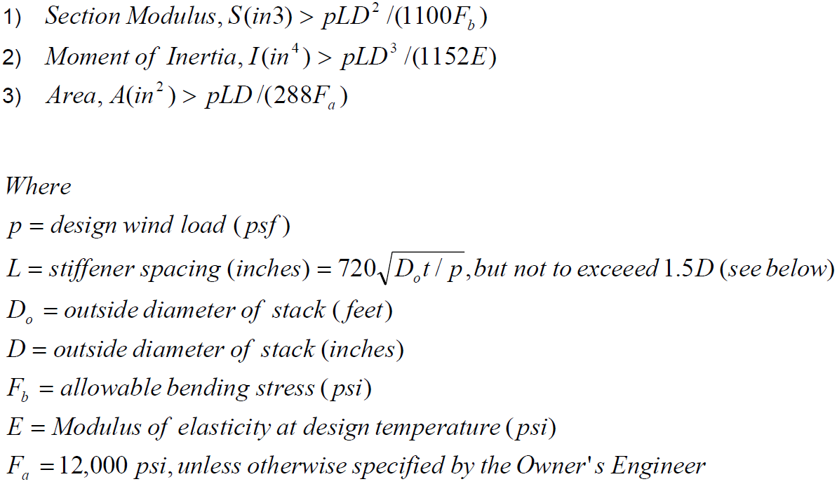
- Stiffener spacing shall not exceed 1.5 times the outside diameter of the stack.
- Openings in stacks shall be limited to a clear width of no more than 2/3 of the outside diameter of the stack.
- A vertical stiffener shall be added on each side of the opening to replace the material removed, see Figure 2 and Figure 3. Vertical stiffeners shall be designed as columns and shall extend far enough above and below the opening to develop the strength of the stiffener. The minimum
sectional area of each stiffener,
Avs , shall be:
Avs
LatDo
2C
Where
La arc length of the opening (inches)
t stack thickness at opening (inches)
Do outside diameter of stack at opening (feet)
C chord length from Figure 3 (inches)
- Horizontal stiffeners in the form of ring girders shall be added above and below the opening as reinforcement, see Figure 2. These girders shall be designed as fixed end beams of span B. Each ring girder shall consist of two full 360-degree stiffeners serving as flanges of the girder, with the stack shell considered the web.
- Joints and Flanges
- Permanent splice joints of stacks shall be designed for the resultant stresses at the joint using double-welded flanges, see Figure 4.
- Flange thickness, t f (inches), shall be per the following formula, but not less than 1/2 inch:
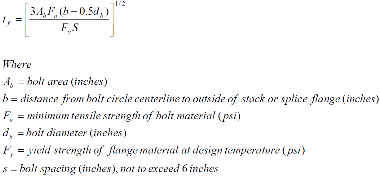
- Bolting shall be ¾-inch diameter minimum. The allowable bolt stress shall be limited to 75% of the allowable tensile strength per the AlSC Specification.
- (*)Leakage shall be prevented by seal welding or use of gaskets approved by the Owner's Engineer.
- Butt welds shall be designed based on allowable stresses given in Table 1.
- Foundations, Baseplates and Anchor Bolts
- Foundations for stacks shall be designed in accordance with EP 4-2-3 and the additional requirements.
- The entire footing area of the reinforced concrete foundation for a stack shall be in compression for the design overturning moment.
- Reinforced concrete foundations shall be protected from hot flue gases.
- Stack base plates shall be designed to resist tension due to the horizontal component of the base cone, if one is used. Maximum ring tension shall not exceed 10,000 psi.
- Base plates shall be sized per applicable formulas and allowable stresses in ASME STS-1 and the AlSC Specification.
- Anchor bolts shall be designed in accordance with EP 4-2-3 and additional requirements of this Practice.
- The minimum diameter of anchor bolts shall be 1-1/2 inches.
- The maximum spacing of anchor bolts shall be 5 feet, with a minimum of eight anchor bolts.
- Appurtenances
- Ladders, platforms and other auxiliary structures on stacks shall be designed in accordance with ASME STS-1 and EP 4-5-3.
- (*)A cleanout door, not less than 2 feet 2 feet shall be provided near the base of the stack. The bottom of the door shall be within 3 feet of the base, unless otherwise approved by the Owner's Engineer. The door shall be suitably reinforced per this Practice.
- (*)Instrument connections shall be made with couplings. Size and location shall be specified by the Owner's Engineer.
- (*)Other appurtenances including, but not limited to, painter's trolley, and dampers shall be specified by the Owner.
- Openings shall not exceed a clear width greater than 2/3 of the stack's outside diameter.
VIBRATION ANALYSIS AND DESIGN
- An analysis of wind-induced vibration (WIV) shall be performed for all stacks with a ratio of effective height/diameter (at the top-most diameter) greater than 5.0 or a fundamental natural frequency less than 1 Hz. The analysis shall be performed in accordance with EP 4-1-1 and the additional requirements of this Practice. The Owner's Engineer may waive the need for WIV analysis if the critical velocity is less than 30 or greater than 70 mph.
- The fundamental natural frequency of the stack shall be calculated in accordance with EP 4-1- 1 and the additional requirements of this Practice.
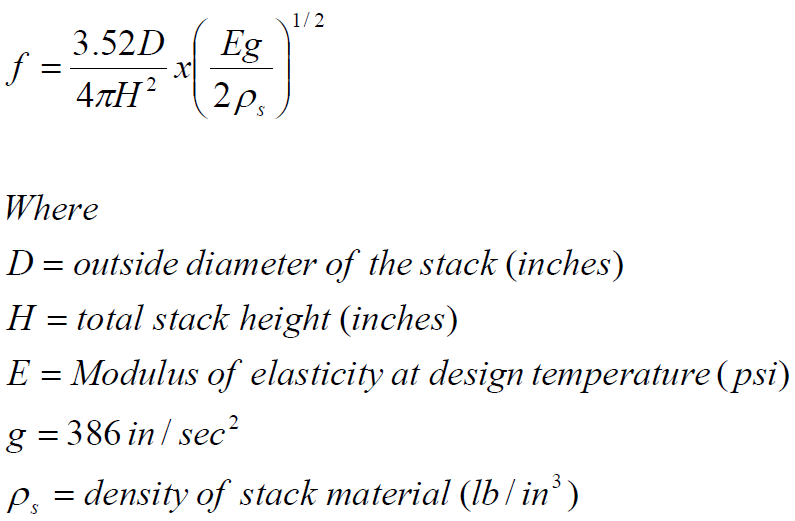
- For unlined stacks for which a uniform cantilever beam assumption is appropriate, the fundamental natural frequency, f, shall be approximated by the equation below. For other configurations, the natural frequency shall be determined by the Raleigh method, or another numerical method that takes into account the mass and stiffness distribution:
- The critical wind velocity (resonance velocity), Vc, for the stack shall be calculated per EP 4-1-1 with the natural frequency determined in accordance with this Practice
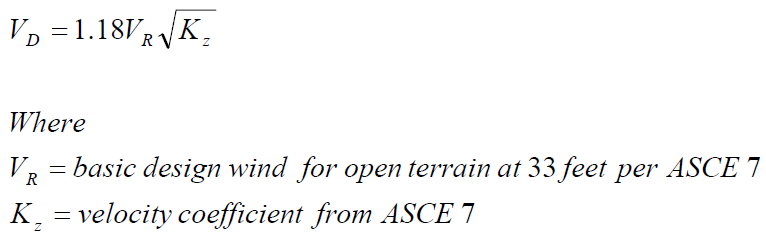
- The mean hourly design wind, VD, shall be determined, with z 5H / 6 , from the following:
- (*)Unless otherwise specified by the Owner's Engineer, WIV shall not be considered if Vc is less than 30 mph or if:
Vc 1.3VD
- If Vc exceeds 30 mph, but is less than 1.3VD , WIV shall be considered as follows:
- The following mass term, m1, shall be calculated:
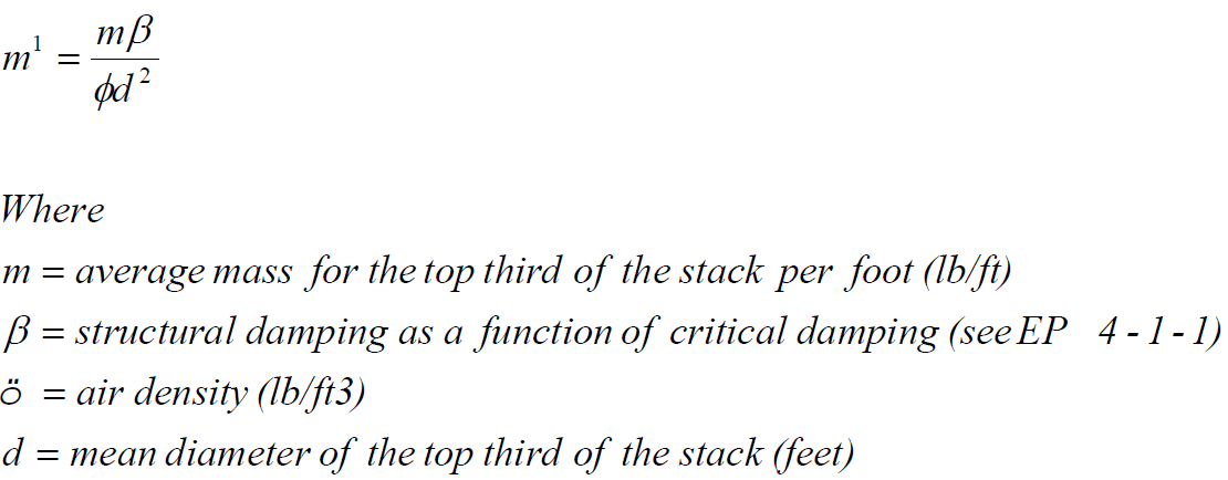
- Large amplitude WIV is probable if m1 0.4. WIV shall be prevented by methods given in this Practice.
- If 0.4 m1 0.8 , significant amplitude WIV is possible. WIV shall be prevented by methods given in this Practice, the design shall be changed to increase Vc 1.3VD , or a detailed vibration analysis and fatigue design shall be performed in accordance with this Practice.
6.7.4 If m1 0.8 , V
0.4VD
, WIV stress may exceed static wind stress. WIV may be prevented by
methods given in this Practice or a detailed vibration analysis and fatigue design shall be performed in accordance with this Practice
6.7.5 (*)Detailed vibration and fatigue analysis shall be performed in accordance with ASME STS-1 and EP 4-1-1. See the British Standard and publications in Section 2.0 for further guidance on this analysis. The actual method of analysis is subject to the Owner's approval.
- In cases where it is impractical to change the critical velocity of the stack such that Vc 1.3VD or less than 30 mph, design features that disturb the creation of vortices and/or dampen WIV shall be considered. Such design features include, but are not limited to, the addition of damping through the use of linings, the addition of damping devices at the base or the top of the stack, the use of damping devices on guy lines, or the use of helical strakes or shrouds. The Owner shall approve the use of any such design feature.
- The design of helical strakes or shrouds shall be in accordance with ASME STS-1.
- The design of damping devices shall be in accordance with ASME STS-1.
- The maximum displacement amplitude at the top of steel stacks shall be in accordance with EP 4-1-1.
- (*)Dynamic lift forces shall be considered in fatigue analyses. Methods to determine these forces shall be reviewed and approved by the Owner's Engineer. Fatigue design shall be based on requirements in EP 4-1-1 unless otherwise approved by the Owner's Engineer
- Ovaling vibration effects shall be considered in all steel stacks.
- Requirements for design for ovaling vibration shall be in accordance with EP 4-1-1.
- If the design wind velocity is such that ovaling is a concern, the thickness of the stack shall be increased to a minimum of D/250 or intermediate stiffeners shall be added to raise the critical velocity for ovaling to 60 mph or greater.
LININGS AND EXTERNAL INSULATION
- (*)Linings and insulation shall be provided when specified by the Owner's Engineer.
- Lining and insulation materials, design and application shall comply with SME STS-1, EP 11-1- 1, EP 11-1-2, EP 11-3-1 and EP 11-3-3, where appropriate, and additional requirements of this Practice.
- Linings shall be of single layer construction.
- Minimum lining thickness shall be 2 inches.
- The top surface of the lining shall be protected from the weather by a stainless steel rain cap.
- Externally insulated stacks shall be provided with a metal jacket insulation covering.
FABRICATION AND ERECTION
- General
Fabrication and erection of stacks and associated structures and equipment shall be in accordance with all applicable drawings and specifications.
- Welding
- All welding shall be in accordance with AWS D1.1.
- An adequate and properly supported platform shall be provided for all site welding. The platform shall be protected from the weather.
- Tolerances
- The maximum deviation from vertical for stacks shall be the lesser of 1.0 inch or 1/1000 of the stack height.
- The maximum out-of-roundness of a stack at any cross section shall be such that the difference between maximum and minimum diameters does not exceed 2% of the nominal diameter of the cross section.
- Misalignment of plates at any joint shall not exceed 25% of the smaller plate thickness or 1/8- inch.
- Vertical joints shall not deviate from a true circle by more than a depth of 1/4 inch as measured from an 18-inch long template, centered at the weld and cut to the prescribed radius.
- Banding of girth welds, defined as localized deviation of the shell from vertical, shall not exceed 3/8 inch, as measured from a 36-inch long straight edge, centered at the weld.
- Mating faces of bolted joints shall provide a metal-to-metal contact with a maximum gap of 1/8- inch at any point. The permissible out-of-squareness is 1/32 inch per inch of flange width.
INSPECTION
- The Inspector reserves the right to inspect materials and workmanship at any time. Approval of the work by the Inspector shall not relieve the Manufacturer or Erector of responsibility for providing a fabricated structure that is in accordance with all drawings and specifications.
- The Manufacturer shall provide mill reports covering the chemical and physical properties of all steel used in the project.
- The Manufacturer shall maintain records of nondestructive testing and qualifications of testing personnel and submit them to the Owner's Engineer.
- The Erector shall provide temporary platforms, ladders and other safety equipment required for access to the stack during field inspection by the Inspector.
- Finished welds shall be examined by spot radiography. Acceptance criteria shall be per Paragraph UW51 (b) of the ASME Boiler and Pressure Vessel Code, Section VIII.
- At least one radiograph shall be made for every two girth seams.
- At least one radiograph shall be taken for every two vertical seams.
- At least two radiographs shall be taken of each welder's work.
- Where radiographs disclose defects, additional radiographs shall be taken on each side of the defect per Paragraph UW52 (d) of the ASME Boiler and Pressure Vessel Code, Section VIII.
- (*)Detective areas shall be repaired, at the expense of the Erector, by methods approved by the Owner. Repaired areas shall be re-inspected.
- (*)Field Inspection results shall be recorded on EP 4-7-1C or an alternative format acceptable to the Owner's Engineer.
10.0 TABLES
TABLE 1
ALLOWABLE STRESSES IN STACK SHELLS (KSI) (1)
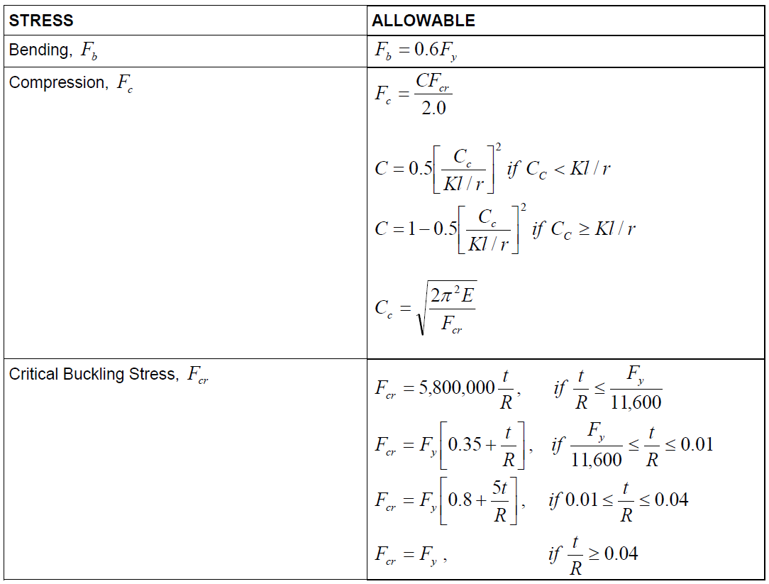
NOTES:
- where t = metal thickness (inches), R= Outside Radius of stack (inches) Fy = yield strength at design temperature (ksi)
- Allowable stresses for components other than the shell shall be in accordance with the applicable ASME STS-1 or the AISC Specification or Code, as appropriate.
- Kl/r is defined as the slenderness ratio per the AISC Specification. With K = 2.0 for a cantilevered member.
- E = modulus at design temperature (ksi).
TABLE 2
CORROSION ALLOWANCES FOR STACKS (INCHES)
| Material/Condition | Internal Corrosion Allowance |
External Corrosion Allowance |
|---|---|---|
| External Condition: | ||
| All Painted Steel | na | 0 |
| Carbon Steel with Insulation | na | 0 |
| Unprotected Carbon Steel | na | 1/8 |
| Unprotected Weathering Steel | na | 1/16 |
| Unprotected Stainless Steel | na | 0 |
| Internal Condition (1),(2): | ||
| Lined or Insulated, under 650°F | 1/16 | na |
| Unprotected, under 650°F | 1/8 | na |
NOTES:
- No Internal allowance required for austenitic stainless steel or non-corrosive service
- (*)Highly corrosive service or service over 650°F and the corresponding internal corrosion allowance shall be specified by the Owner.
TABLE 3
DOCUMENTATION REQUIREMENTS FOR STEEL STACKS PER EP 4-7-1
| Item | Description | Format | As-Built |
|---|---|---|---|
| 1 | Design calculations submitted for approval. | Text | N/A |
| 2 | Plan, elevation and detail drawings. | See EP 2-5-2 | Yes |
| 3 | Procedures for dynamic wind analysis submitted for review. | Text | N/A |
| 4 | Mill test reports. | Text | N/A |
| 5 | Records of NDE and qualifications of testing personnel. | Text | N/A |
| 6 | Results of field inspection. | Text | N/A |
11.0 FIGURES
FIGURE 1
EQUIVALENT RADIUS OF TAPERED SECTION
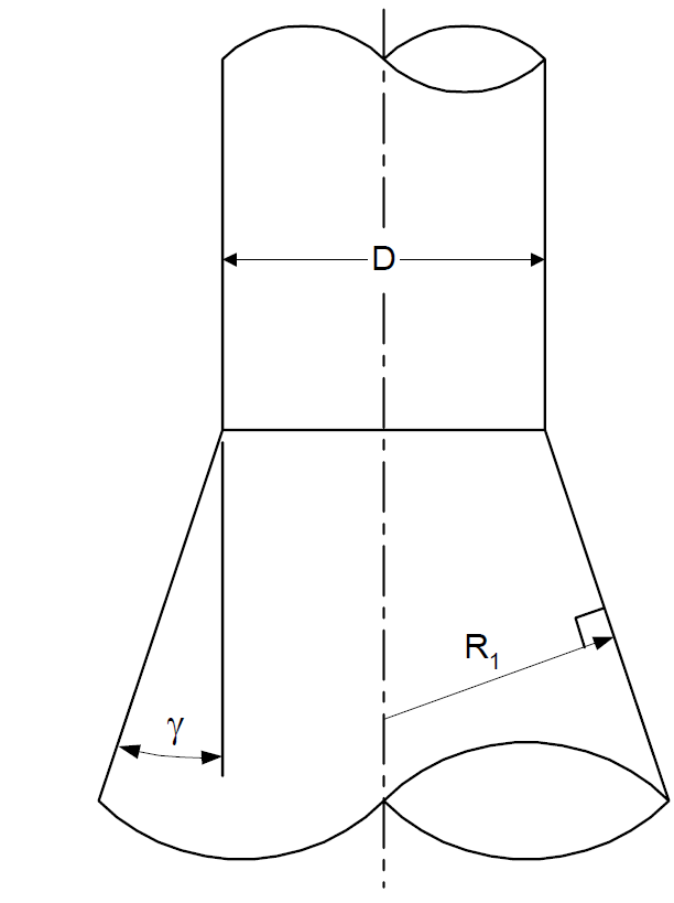
NOTES:
R1 = Equivalent radius
D = Diameter of cylindrical section
g = One-half apex angle of conical section
FIGURE 2
REINFORCEMENT OF STACK OPENING – ELEVATION
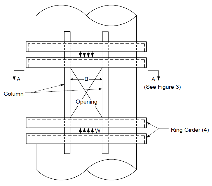
FIGURE 3 REINFORCEMENT OF STACK OPENING – PLAN
NOTE:
Geometry definitions used in Paragraph 5.2.7.
FIGURE 4
FLANGE STACK SPLICE JOINTS
Notes:
tf = Flange thickness per Paragraph 5.3.1a (in.). db = Bolt diameter (in).
b = Distance from outer shell or flange face to bolt centerline.
© 2026 Inflection Point Engineering, LLC. All rights reserved. The content of this page — including calculation methods, reference data, written analysis, interactive tools, and source code — is the intellectual property of Inflection Point Engineering, LLC and is protected under applicable copyright, trademark, and trade secret laws. Unauthorized reproduction, redistribution, modification, or derivative use in whole or in part is prohibited without prior written consent.
Disclaimer. This material is provided for informational and educational purposes only and does not constitute professional engineering advice. Calculations, reference data, and methodologies are based on published standards and accepted engineering practice but are not a substitute for engineering judgment, site-specific analysis, or review by a licensed Professional Engineer. Inflection Point Engineering, LLC makes no warranties, express or implied, regarding the accuracy, completeness, or fitness for a particular purpose of any content presented here, and shall not be liable for any direct, indirect, incidental, or consequential damages arising from its use. Users assume all risk associated with applying this content to real-world design, operations, or decisions.
© 2026 Inflection Point Engineering, LLC. All rights reserved.