 Section 4 — Structures and Foundations
Auxiliary Structures for Operation and Maintenance
IPE Engineering Practice IPE-EP-4-5-3
Document number: IPE-EP-4-5-3 · Section: 4 — Structures and Foundations
Figure 12 Ladder Safety Gate 37
Figure 13A Typical Handrail Detail 38
Figure 13B Removable Handrail Section Detail 39
Figure 14A Typical Handrail , Floor Plate and Grating Connections 40
Figure 14B Typical Handrail, Floor Plate and Grating Connections - Continued 41
Figure 15A Floor Grating Arrangement In Structures - Plan View 42
Figure 15B Floor Grating Arrangement In Structures - Sections 43
Figure 15C Floor Grating Arrangement In Structures - Cutout Reinforcement 44
Figure 16 Stair Details - Grade to Platform 45
Figure 17 Stair Details - Platform to Platform 46
Figure 18 Stair Stringer Details 47
Figure 19 Stair Tread Detail 48
Figure 20A Wooden Crossover - Elevation 49
Figure 20B Wooden Crossover - Detail and Sections 50
Figure 21 Concrete Figure 51
Figure 22A Steel Crossover - Elevation 52
Figure 22B Steel Crossover - Plan and Detailstank Ladder Figure 53
Figure 23 Tank Ladder Details 54
Figure 24 Railing at Foam Chambers for Fixed Roof Figure 55
Figure 25 Wing Railing for Fixed Roof Figure 56
SCOPE
- This Practice covers mandatory requirements governing the use, design, and layout of auxiliary structures and facilities, such as walkways, platforms and ladders, provided for access and maintenance of plant equipment.
- Any deviation from this Practice must be approved by the procedure described in EP 1-1-3.
- An asterisk (*) indicates that a decision or approval by the Owner or the Owner's Engineer is required or that additional information is furnished by the Purchaser.
- A revision bar indicates all changes made to this Revision.
- Documentation required in accordance with this Practice is given in Table 4.
2.0 REFERENCES
The latest edition of the following standards and publications are referred to herein.
STANDARDS AND PUBLICATIONS
| IPE Engineering Practices |
|---|
| EP 1-1-3 Deviations to IPE Engineering Practices EP 3-1-1 S&L P Philosophy EP 4-1-1 Design Criteria and Loads for Structures EP 4-2-9 Grouting and Base Plates for Structural Steel and Equipment EP 8-4-1 Cooling Towers EP 9-1-1 Atmospheric Storage Tanks EP 10-3-1 Shop Painting EP 10-3-8 Galvanized Coatings |
| ASTM |
| A123 Zinc (Hot Dip Galvanized) Coatings on Iron and Steel Products |
| IBCO |
| Uniform Building Code |
| OSHA Standards |
| Subpart D Walking - Working Surfaces 1910.23 Guarding Floor, Wall Openings and Holes 1910.24 Fixed Industrial Stairs 1910.27 Fixed Ladders |
DEFINITIONS
- Accessways - Clear unobstructed paths required to perform routine plant operations and maintenance.
- Contractor - Company or business that agrees to furnish materials or perform specified services at a specified price and/or rate to the Owner.
- Equipment - Each pump, compressor, product accumulator vessel, pressure relief device, valve, sampling connection system, open-ended valve or line, flange or other connector in vOC service, or devices or systems required by this Practice.
- Manufacturer - The recipient of a direct or indirect purchase order for materials and/or equipment. In this context, a direct order is one issued to a manufacturer by a contractor or the Owner. An indirect order is one issued to a manufacturer by a vendor (recipient of a direct order) for materials, fabricated components, or subassemblies.
- Owner - Inflection Point Engineering, LLC.
- Owner's Engineer - A Inflection Point Engineering, LLC appointed engineer.
GENERAL DESIGN
- (*)The minimum access requirements for equipment and facilities are given in Table 1. The Owner's Engineer shall specify additional access requirements on an as needed basis.
- The minimum dimensions, width, headroom, etc. associated with ladders, platforms, walkways and stairs are stipulated in Table 2.
- Design loads and criteria for all auxiliary structures for operation and maintenance shall be in accordance with EP 4-1-1.
- (*)All structures provided to this Practice shall be in accordance with the latest applicable OSHA requirements and the requirements of all state and local codes and jurisdictions. In case of conflicts, the most stringent requirements, as specified by the Owner's Engineer, shall apply.
- All auxiliary structures for operation and maintenance fabricated from structural steel shall be galvanized in accordance with EP 10-3-8, and/or painted in accordance with EP 10-3-1, as applicable.
PLATFORMS
- General
- Platforms are typically required to access valves, instruments, blinds, etc. on reactors, towers and furnaces. In general, platform elevations are determined by the items that require operation and maintenance. Platform elevations on tall reactors are set in accordance with a maximum ladder run length of 30 feet. Reactor platforms are normally rectangular and primarily located at the intermediate locations and top head of the reactor.
- Tower platforms are normally circular and partially encircle the tower. Areas that are not encircled by platforms are reserved for ladders or piping runs. Usually, one sector of the tower diameter is open for unobstructed vertical piping runs, see Figure 1. Maintenance platforms at tower manways should provide adequate clearance to swing open the maintenance access cover flange. The minimum recommended clearance between the face of the manway cover and equipment e.g., control valves, or handrail is 3 feet. Typical tower platform and ladder elevation requirements are shown in Figure 2.
- Furnace platforms are either circular or rectangular depending on the furnace design. A circular furnace has 360 degree full circle platforms at the firing level and convection section level. Rectangular furnaces usually require a full encompassing platform at the radiant section level for access to observation doors. Platforms around furnaces shall allow plant personnel free unobstructed area at and around piping manifolds, instruments, and furnace appurtenances.
- Platforms shall be provided around horizontal and vertical exchangers to allow access for removal of related equipment components during maintenance.
- Additional requirements for tank platforms shall be per EP 9-1-1 and the following:
- Guard railings and toe plates shall be per this Practice and Figure 23 and Figure 25.
- For fixed roof tanks, guard railings shall be installed along the edge of the roof, extending at least 6 feet beyond the platform in each direction.
- (*)For floating roof tanks, guard railings shall be furnished for windgirders that are specified by the Owner's Engineer to be used as walkways.
- A platform shall be provided adjacent to the tank at the top of the ladder or stairway. On fixed roof tanks, this platform shall be level with the edge of the tank roof.
- A railing shall be provided at each foam chamber on a fixed roof tank in accordance with Figure 24.
- Wing railings shall be provided along the roof edge at any access entrance on a fixed roof tank in accordance with Figure 25.
- Additional requirements for access to cooling towers shall be per EP 8-4-1 and the following:
- For counterflow towers, access shall be provided to drift eliminators, the water distribution system, and fans for each cell by means of a ladder from the fan deck. There shall be one access door for each fan assembly. The minimum size of access openings through the fan deck shall be 24 by 30 inches.
- For crossflow towers, doors and walkways shall be provided at the basin level for access to the tower interior and interior walls. Walkways shall extend the length of the tower on both sides of the center partition wall. Access and walkways shall also be provided to each individual cell, cell fan, and fan gear reducer.
- For fan stacks higher than 6 feet, access to fans, gears, and couplings shall be provided by removable sections or doors in the stacks. These sections shall be of sufficient size to permit removal of the fan hubs and speed reducers.
- At least one stairway and one ladder, each located at opposite ends of the tower, shall be provided that extend to ground level. Stairway and ladder dimensions shall be in accordance with additional requirements of this Practice.
- A handrailing, consisting of a top rail and a mid rail, shall be provided on stairways, and around the fan deck and water distribution deck. A toeboard shall be provided around the fan deck and water distribution deck.
- Minimum clear platform widths shall be as stipulated in Table 2, except as follows:
- (*)In front of manholes for servicing trays: 3 feet 0 inches. For manholes used for other purposes (such as ventilating equipment) widths shall be specified by the Owner's Engineer.
- At each end of the shell and tube units for servicing bonnet, channel, and tube bundle: 4 feet 6 inches.
- Around elevated machinery: 3 feet 0 inches.
- The clear platform width for servicing special parts of equipment, such as retractable water sprays, shall be based on the requirements for operability and maintenance.
- (*)The space on platforms used for permanent or temporary storage of containers of catalyst, chemicals, and similar materials will be specified.
- Platforms around compressors and other large machinery shall provide space for placement of rotors and similar components.
- When welding terminal boxes are located on process unit structures, space shall be available on the platform (served by the welding box) sufficient to accommodate one welding machine.
- Platforms dedicated to instrument maintenance shall have a minimum clear length of 3 feet.
- Platforms servicing manholes shall not be more than 3 feet 6 inches below the manhole centerline and shall have a minimum clear length of 6 feet 0 inches measured at the face of the manhole flange. Platforms servicing manholes shall also extend a minimum of 4 feet 0 inches from the manhole centerline on the davit side.
- Platforms for structures shall be as follows:
- (*)For steel structures, grating shall be used, except that floor plate shall be used when platforms or walkways cross over high fire risk areas. The Owner's Engineer shall specify high fire risk areas.
- For concrete structures, platforms shall be concrete or floorplate.
- For all compressor platforms, grating shall be used.
- Platform floor plate shall have a raised pattern and 1/4 inches nominal thickness. Drainage shall be provided by one hole, 1/2 inches diameter, for approximately every 15 square feet of steel floor plate. Holes shall be located at low spots, and shall be drilled after erection. Where practical, drainage holes shall not be located directly above ladders and plate stair treads.
- (*)Proposals to use a rolling stair/platform in lieu of permanent structures for access to equipment near grade shall be approved by the Owner's Engineer.
- (*)The Owner's Engineer shall approve the use of operating and service platforms interconnecting two or more equipment items (such as elevated towers) or facilities.
- (*)The final number and arrangement of platforms, including access and exit locations, shall be reviewed by the Owner's Engineer.
- Platform Safety Clearances
- The minimum distance of the platform below the top of any stack or continuously operating vent in other than steam or air service is 12 feet within a horizontal 70 foot radius from the outside edge of the stack. Platforms allowing unrestricted access located outside of this radius shall be at least 12 feet below a line extending upwards 45° from the horizontal (projected top of the stack) at the end of the 70 foot radius, see EP 3-1-1. (Does not apply to platforms within 500 feet of flare stacks. See EP 3-1-1 for heights of platforms and flare stacks within 500 feet of each other.)
- The minimum distance of the platform below the outlet piping for general relief and safety vents operating in other than steam or air service is 12 feet within a horizontal radius of 20 times the outside diameter of the vent (5 feet min., 35 feet max.). This shall be measured from the outside edge of pressurized relief or vent outlet piping. Platforms allowing unrestricted access located outside of this radius shall be at least 12 feet below a line extending upwards 45° from the horizontal (projected top of the vent) at the end of the determined horizontal radius.
STAIRWAYS AND LADDERS
- (*)The primary access and egress to main operating levels in structures, buildings, and furnaces shall be by stairway. Access to platforms shall be by stairway if such access is required for routine operation or maintenance of the unit. Access to platforms for non-routine operation or maintenance of the unit shall be by stairway or ladder. A means of escape in addition to the usual access shall be provided from platforms where travel to an access exceeds 50 feet, or where a dead end would otherwise exist, or in a high-risk area. The dead end or high-risk area shall be specified by the Owner's Engineer.
- Stair landings shall not be less than 2 feet 6 inches in the direction of the stairway.
- Stairways shall meet the following:
- Maximum angle with a horizontal line shall be 45 degrees.
- Minimum tread width shall be 9-3/4 inches.
- Minimum effective width of stair shall be 2 feet 6 inches.
- Stair treads shall be hot-dip galvanized with a non-slip surface and nosing.
- Ladders, railing, toe plates, safety cages, and similar items shall be designed as per Occupational Safety and Health Administration (OSHA), except as modified below:
- A safety cage shall be provided on ladders extending more than 20 feet above grade. See Figure 3A. Safety cages or special guards shall also be provided for ladders originating on a platform if the ladder height is less than 20 feet but its proximity to the platform edge is such, that a man might fall more than 20 feet to some other platform or the ground.
- Safety gates shall be provided across ladder openings at each platform landing.
- Ladder safety devices shall not be used in lieu of cage protection.
- Pipe railings shall be seal-welded to prevent internal corrosion.
- Minimum clear length of ladder rungs shall be 18 inches.
- The minimum vertical clearance above a ladder measured from the platform shall be 7 feet 0 inches.
- Ladder access shall be designed as follows:
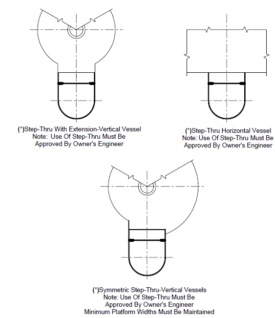
- (*)Where ladders are the only means of access, they shall provide for side-step access to platforms unless through-ladder type is approved by the Owner's Engineer.
- Where ladders serve as a secondary access to platforms, they may be either the side-step or through-ladder type installation.
- Additional requirements for tank stairways and ladders shall be as follows:
- Tanks requiring gaging or sampling from the roof shall be provided with a spiral stairway and a platform for access to gage or sampling hatch.
- A spiral stairway shall be provided for access to floating roof tanks. In addition, a top platform with a guard railing shall be provided from the top of this stairway to the gage well and the roof ladder.
- Stairway design and construction shall include the following:
- Maximum angle with a horizontal line shall be 45 degrees.
- The run-to-rise ratio shall be 10:8, measured at the center of the tread.
- The minimum effective width of stair shall be 2 feet 6 inches, except where connecting to 2-foot wide walkways in which case the effective width shall be 2 feet.
- Stair landings shall not be less than 2 feet 6 inches, in the direction of the stairway.
- For vertical rises over 30 feet, an intermediate landing is required.
- Tanks not equipped with spiral stairway shall be provided with an external vertical ladder, see Figure 23.
- Roof ladders for floating roof tanks - If the tank diameter is equal to or greater than the height, a rolling type roof ladder shall be furnished having a minimum angle of 30° from the vertical. If the tank diameter is less than the tank height, it shall have a vertical roof ladder. Rolling roof ladders shall meet the following requirements:
- The track shall be raised from the roof to an elevation that will assure it will not be immersed in water that accumulates on the roof.
- On pontoon-type roofs the ladder track shall be point supported to allow maximum flexibility of the pontoon and deck areas.
- One point-support shall be located near the center roof drain sump to improve drainage.
- The rolling ladders shall be electrically grounded to the tank shell or gaugers platform. The rolling ladder track shall be electrically grounded to the roof.
- (*)Unless otherwise approved by the Owner's Engineer, rolling ladders shall be equipped with self-leveling, stairway-type treads. The self-leveling mechanism design shall maintain the treads level within ±1/4 inch over the width, during the total roof travel.
- Parts such as axles, pivots, pins, etc., shall be stainless steel.
- Railings for rolling ladders shall be NPS 1-1/2 Sch 40 pipe, or 2x2x3/8 inch steel angle.
6.6.6 If a permanent ladder is specified for access from the roof to the internal floating cover, it shall be designed to accommodate the full travel of the floating cover.
6.7 Additional ladder design requirements shall be per Table 1.Table 1
ACCESS WALKWAYS
- Walkways shall be provided where in-plant personnel are likely to pass through while carrying out routine duties. Walkways shall also be located to provide an additional means of egress for platform clusters located in process units.
- (*)The Owner's Engineer shall specify specific requirements for walkways and their location.
- (*)If platforms are provided at the tops of ladders or stairways on tanks, they shall be interconnected with walkways arranged so that personnel are not required to walk across the roof of any tank, unless otherwise specified by the Owner's Engineer. Elevated tank roof walkways shall be furnished on the single deck portion of pontoon-type floating roofs to provide dry access from the end of the rolling ladder to the pontoon area.
CROSSOVERS FOR EARTHEN DIKES
- Wooden Crossovers
- The design loads for wooden crossovers shall be per EP 4-1-1. The design criteria shall be in accordance with the Uniform Building Code, or the local building code required by the jurisdiction, and the additional requirements of this Practice.
- Posts, handrail posts, handrails, stringers and tread cleats shall be penta-treated No. 2, milled, Southern Yellow Pine. Stair treads and platform planking shall be penta-treated No. 2, rough, Southern Yellow Pine.
8.2 Steel and Concrete Crossovers
The design of steel and concrete crossovers shall be in accordance with Table 2.
PERMANENT HANDLING FACILITIES
- (*)Built-in handling facilities shall be provided for the following equipment if it is not accessible to mobile handling facilities as determined by the Owner's Engineer:
- Davits shall be provided for handling safety valves weighing 50 pounds or more if no other overhead handling facility is available.
- Facilities shall be provided for servicing channel, bonnet, and tube bundles of tubular units located on the ground under a structure, and for tubular units located at an elevated level in a structure.
- As determined by the final layout, trolley beams or cranes shall be used to service large pumps, motors, turbines, compressors, and similar equipment which are housed or otherwise inaccessible. These lifting facilities shall be extended beyond equipment foundations or into drop-out areas, to permit lowering machinery components to mobile handling equipment at grade level. Provisions for removable sections of walls or roofs enclosing such equipment, to allow access by mobile lifting equipment, are not acceptable substitutes for built-in handling facilities.
- Removable sections shall be provided in railings and flooring of platforms where required for maintenance of auxiliary equipment.
- (*)Trolley beams shall be provided for handling the following equipment, if not accessible to mobile handling equipment, as determined by Owner's Engineer:
- Heavy slide valves.
- Heavy piping components, such as expansion joints, requiring maintenance or repair, when sufficient platform framing or working area is not available for temporary rigging.
- Tubes and similar materials for re-tubing equipment that cannot be lowered to the ground for servicing, such as waste heat boilers of fluid catalytic cracking units.
- Tubes and fittings of fired heaters.
- Manhole covers shall be hinged or equipped with handling davits.
- A trolley beam or a davit shall be located at the top of a tower for handling tower internals and safety valves weighing 50 pounds or more. Orientation of davit and manholes shall be such that:
- Internals removed through manholes are accessible for lifting by davit.
- Drop-out areas provided at the tower are accessible to mobile equipment.
- (*)Trolleys shall be as specified by Owner's Engineer.
- Trolley beam and davit (except manhole davits) working capacities shall be clearly marked.
FABRICATION DETAILS
- (*)Fabrication details for auxiliary structures for operation and maintenance shall be in accordance with the Figures referenced in Table 3, unless otherwise approved by the Owner's Engineer. Plan, elevation, and detail drawings as required for fabrication and erection, shall be provided.
- (*)Details for auxiliary structures for operation and maintenance that are not covered in Table 3 shall be submitted to the Owner's Engineer for review and approval.
11.0 TABLES
TABLE 1
ACCESS PROVISIONS FOR EQUIPMENT
| ACCESS PROVIDED | EQUIPMENT ITEM |
|---|---|
| Permanent Ladder | Check valves--all sizes (at vessels) Gate and Globe valves-NPS 3 and smaller (at vessels) Gauge glasses and trycocks Handholes Instruments Take-off valves Temperature instruments on vessels Level controls between 7 feet and 12 feet above grade Furnace observation doors between 7 feet and 12 feet above grade |
| Permanent Platform | Machinery mounted on elevated platforms Heat exchanger cover, channels, or bonnet flanges (1) Manholes, service and inspection openings (1) Process blinds (1) Relief valves (vertical vessels) all sizes Relief valves (horizontal vessels) all sizes Clean out points Furnace soot blowers Furnace burners when inaccessible from grade Furnace observation doors (1) Furnace sample ports (1) Emergency isolation (block) valves (EBv) Groups of valves at battery limits in elevated pipe racks Gate and Globe valves-NPS 4 and larger (at vessels) Motor operated valves Instrumentation and Controls which require operator attention Control valves--all sizes Level controllers (1) Sampling devices on vessels (1) |
| Mobile Stair | All servicing between 7 feet and 12 feet above grade except as noted herein |
TABLE 1
ACCESS PROVISIONS FOR EQUIPMENT (CONTINUED)
| ACCESS PROVIDED | ITEM OF EQUIPMENT |
|---|---|
| No permanent access | Nozzles on vessels (2) Block valves in yard banks Metal temperature measuring points on vessels Temperature and pressure points in piping for board mounted gages Orifices in lower yard banks Check valves not at vessels Silencers Exhaust heads |
| Temporary platform supports |
Furnace header boxes containing removable plugs and air coolers |
NOTES:
- (*)When less than 12 feet above grade, the Owner's Engineer may waive the requirement for a permanent platform for infrequently accessed equipment, in lieu of the use of mobile stairs or scaffolding.
- (*)Unless otherwise specified by the Owner's Engineer.
TABLE 2
DIMENSIONS FOR ACCESS WALKWAYS, PLATFORMS, LADDERS, AND MAINTENANCE MINIMUM DIMENSIONS, EXCEPT AS OTHERWISE NOTED
| ITEM | DIMENSION DESCRIPTIONS | DIMENSIONS |
|---|---|---|
| Accessways | Headroom height over stairs, platforms, walkways, passageways, and working areas. Headroom is measured to the lowest point of overhead structural framing (including fireproofing), piping (including insulation), and equipment. |
7'-6" |
| Access Walkways |
Headroom height for projections over platforms, walkways, passageways, and working areas |
7'-0" |
| Width of stairways (back to back of stringers) | 2'-6" | |
| Width of landings (in direction of stairways) | 3'-0" | |
| Width of walkways (at grade or elevated) | 2'-6" | |
| Width of elevated walkways receiving traffic from two or more routes | 4'-0" | |
| Maximum vertical rise of stairways (one flight) | 15'-0" | |
| Maximum horizontal distance from any point on platform to an emergency escape |
75'-0" | |
| Maximum length of dead-end platforms in escape routes (1) | 20'-0" | |
| Platforms (1) |
Maximum variance in platform elevations without intermediate step | 9" |
| Minimum clearance width of platforms (6) | 2'-6" | |
| Width of manhole platforms on vertical vessels shall be the greater of width between inside radius and inside of platform on vertical vessels (10") |
3'-0" or one manhole diameter + 12" |
|
| Ladders (2), (3), (4), (6) |
Maximum vertical rise of operational ladders (single run) | 30'-0" |
| Maximum allowable slope of ladders from vertical | 15 | |
| Toe clearance from centerline of rung to obstruction | 8" | |
| Clear climbing space for 90° pitch ladders (3) | 2'-6" | |
| Width of ladders | 1'-6" | |
| Clear climbing space for 75° pitch ladders (3) | 3'-0" | |
| Operation and Maintenance |
Access to equipment, valves, instruments, and manholes located within 7 ft. to 12 ft. above grade |
(5) |
NOTES:
- (*)Dead-end platforms greater than 20 feet long are prohibited where such dead ends are in escape routes or where it may be reasonably anticipated that, because of confusion arising from an emergency or panic situation, an individual
might select an escape path which would lead to such a dead end. The dead end shall be specified by the Owner's Engineer.
- Ladders that are located at, or extend 8 feet or more above grade should be provided with safety cages. Ladders that are located at, or extend less than 8 feet above grade should be provided with top rail hoops only. Ladders that are located at, or extend less than 7 feet above grade do not require a top rail hoop.
- The clear climbing space required for ladders that deviate in pitch between 75° and 90°, shall vary inversely with the pitch between the limits shown for these items.
- Clear climbing space is defined as the climbing area clearance for caged ladders, and shall be provided throughout the length of the ladder.
- One 6 feet high mobile stair stand shall be available for each 10,000 square feet of process area for access to equipment, valves, instruments, and manholes located within 7 feet to 12 feet above grade.
- See section 5.1.7 for exceptions to minimum width.
TABLE 3 FABRICATION DETAIL REFERENCES
| ITEM | FIGURES |
|---|---|
| vessel Platform | 3A, 3B, 3C |
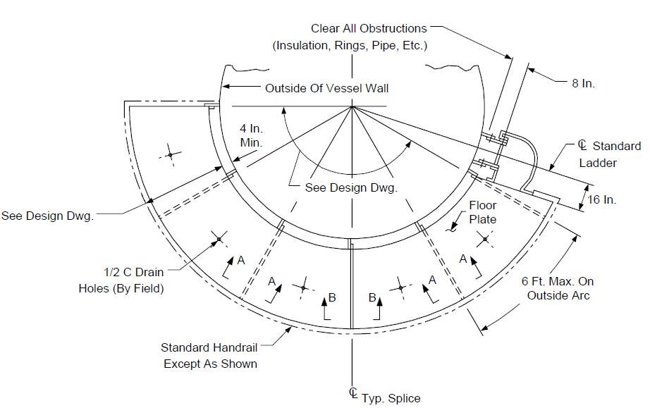
| Platform Arrangement for vertical vessels | 4 |
| Pipe Opening Floor Cover | 5 |
| Platforms at the Top of vessels | 6 |
| Platforms at Elevated Heat Exchangers | 7 |
| Ladder and Cage Arrangement | 8A, 8B, 8C, 8D |
| Ladder Support from Shell of vertical vessel | 9 |
| Ladder Support Details for vertical vessels | 10 |
| Ladder and Cage details | 11A, 11B, 11C, 11D |
| Ladder Safety Gate | 12 |
| Typical Handrail Detail | 13A, 13B |
| Typical Handrail, Floorplate and Grating Connections | 14A, 14B |
| Floor Grating Arrangement in Structures | 15A, 15B, 15C |
| Stair Details - Grade to Platform | 16 |
| Stair Details - Platform to Platform | 17 |
| Stair Stringer Details | 18 |
| Stair Tread Detail | 19 |
| Wooden Crossover | 20A, 20B |
| Concrete Crossover | 21 |
| Steel Crossover | 22A, 22B |
| Tank Ladders and Railing | 23, 24, 25 |
TABLE 4 DOCUMENTATION REQUIREMENTS FOR AUXILIARY STRUCTURES FOR OPERATION AND MAINTENANCE PER EP 4-5-3
| Item | Description | Format | As-Built |
|---|---|---|---|
| 1 | Fabrication drawings in accordance with paragraph 10.1. | See EP 2-5-2 | Yes |
| 2 | Details for auxiliary structures not covered in Table 3 of this Practice. |
See EP 2-5-2 | Yes |
12.0 FIGURES
FIGURE 1
TOWER AREAS OF DIVISION
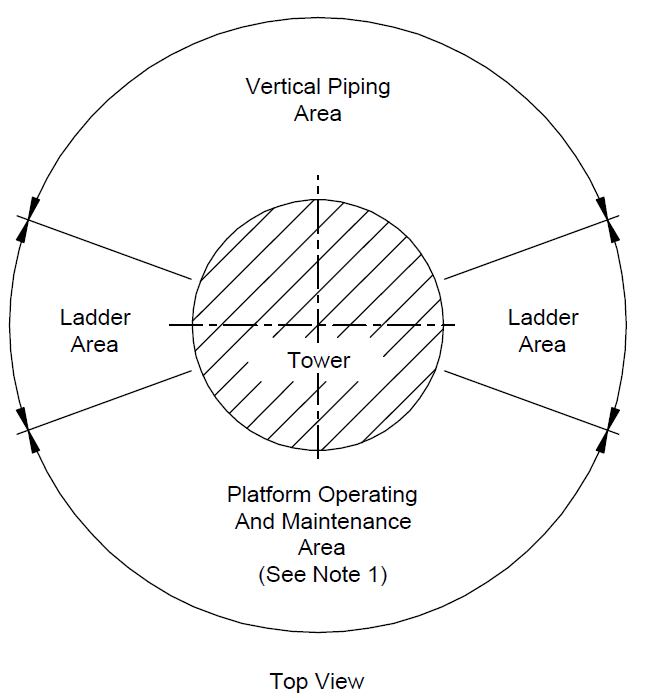
NOTES:
(1) Platform operating and maintenance area shall face crane access area.
FIGURE 2
TYPICAL TOWER PLATFORM AND LADDER ELEVATIONS
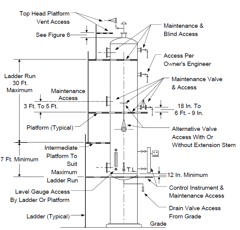
FIGURE 3A
VESSEL PLATFORM - PLAN VIEW
NOTES:
(1) See Figure 3C for sections.
FIGURE 3B
VESSEL PLATFORM - TYPICAL SECTIONS
NOTES:
- Checkered floor plate shown; grating may be used, see Figure 3D.
- Strength of shell shall be checked for applied platform loads.
(2) See Figure 3C for details.
FIGURE 3C
VESSEL PLATFORM - SECTION AND DETAILS
NOTES:
- Checkered floor plate shown; grating may be used.
- Holes in floor plate shall be 9/16-in. diameter, countersunk for ½-in. diameter flat head machine screws on 18-in. centers. Holes shall be drilled by the Manufacturer. Field drill and tap all supporting members.
- Floor plate shall be provided with drain holes per Figure 14A.
FIGURE 3D
VESSEL PLATFORM - TYPICAL SECTION WITH GRATING
NOTES:
- Grating shall be serrated Irving Type IWA or Owner's Engineer approved equal with 1 1/4 in. x 3/16 in. main bars at 1 3/16 in. o.c. with cross bars at 4 in. o.c.
- Strength of shell shall be checked for applied platform loads.
- See Figure 3C for details.
FIGURE 4A
PLATFORM ARRANGEMENTS FOR VERTICAL VESSELS
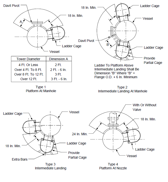
FIGURE 4B
OTHER ACCEPTABLE VESSEL PLATFORM ARRANGEMENTS - PLAN VIEW
NOTES:
(1) See also Notes on Figure 4A.
FIGURE 5
PIPE OPENING FLOOR COVER
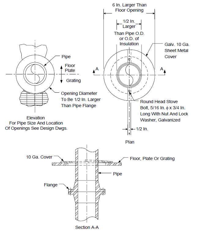
FIGURE 6
PLATFORMS AT THE TOP OF VESSELS
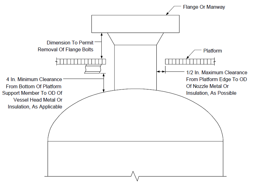
FIGURE 7
PLATFORMS AT ELEVATED HEAT EXCHANGERS
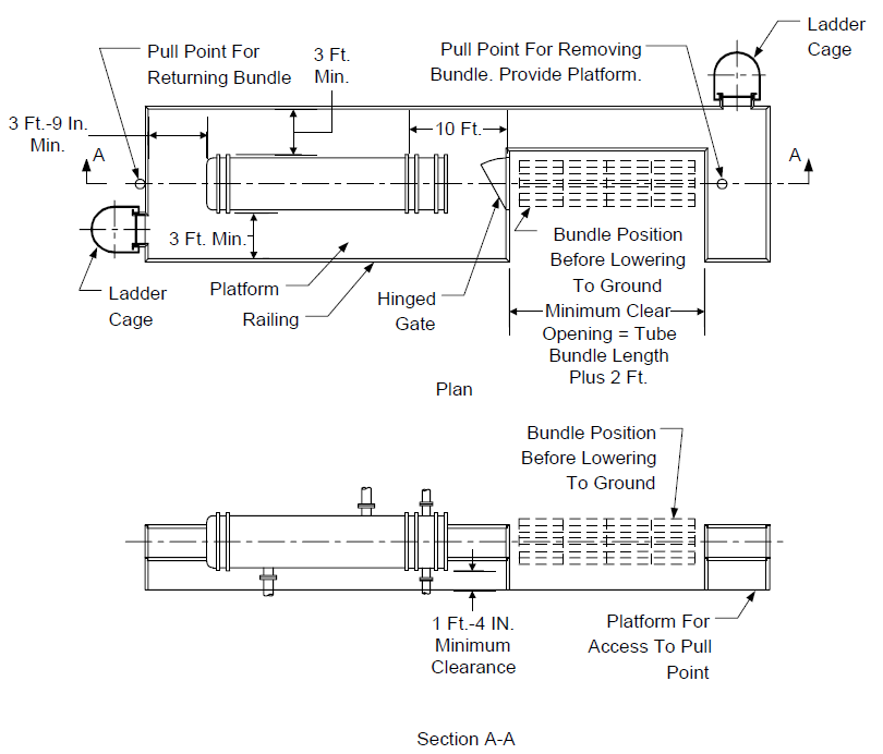
NOTES:
- It is intended that permanent lifting facilities shall be installed in conjunction with exchanger platforms.
- (*)The Owner's Engineer will specify if a platform is required in this length for bundle pulling.
FIGURE 8A
LADDER AND CAGE ARRANGEMENT
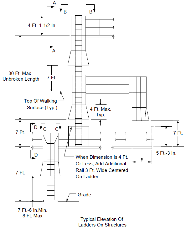
FIGURE 8B
LADDER AND CAGE ARRANGEMENT - SECTIONS
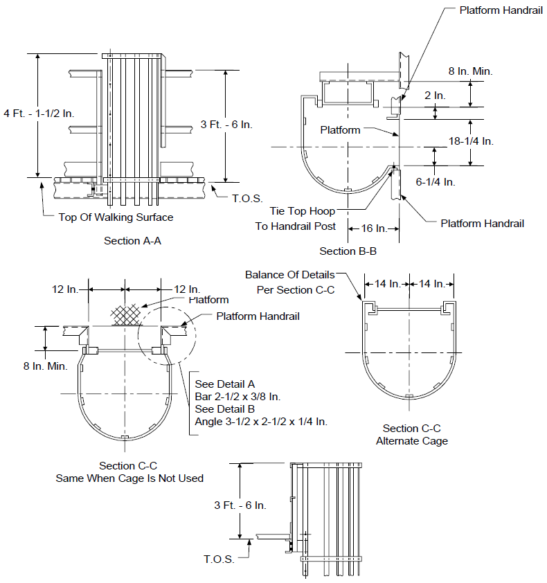
FIGURE 8C
LADDER AND CAGE ARRANGEMENT - DETAILS A AND B
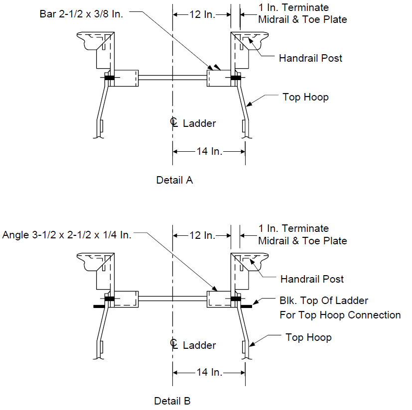
FIGURE 8D
LADDER AND CAGE ARRANGEMENT
TYPICAL LADDER CONNECTION TO STRUCTURE DETAILS
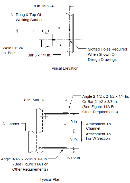
FIGURE 9
LADDER SUPPORTED FROM SHELL OF VERTICAL VESSEL
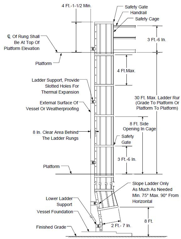
FIGURE 10
LADDER SUPPORT DETAILS FOR VERTICAL VESSELS
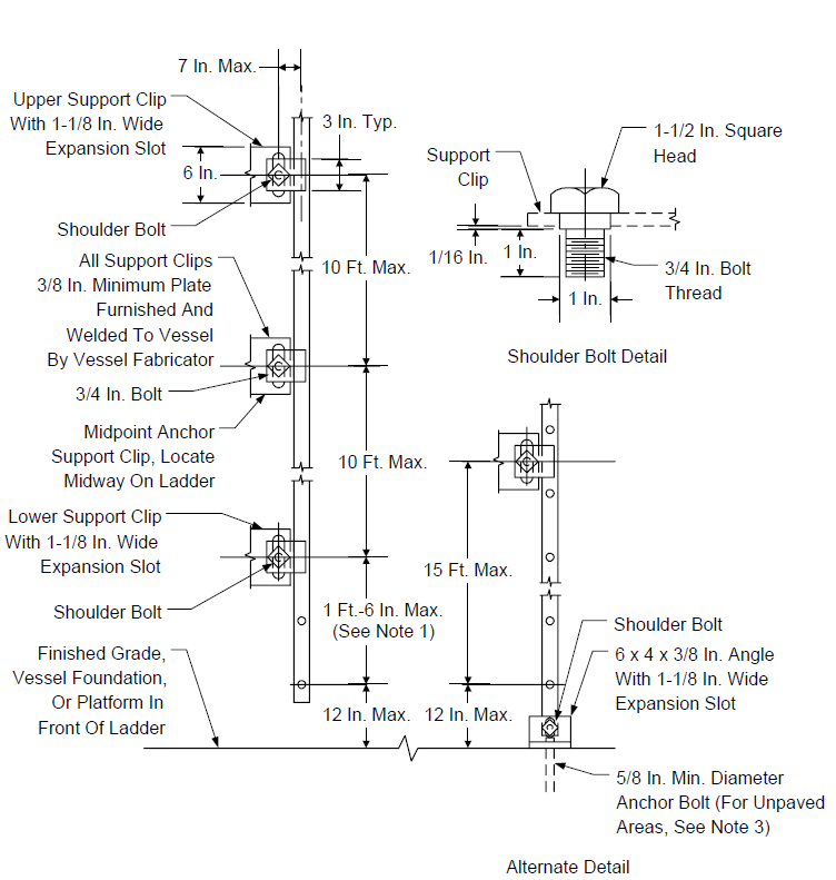
NOTES:
- When ladder is attached to equipment operating at less than 120°F, support clips shall not be slotted and ordinary bolts, rather than shoulder bolts, shall be used.
- Use alternate detail only when the ladder extends more than 2 ft. below the lowest support.
- When the area at the foot of the ladder is unpaved a footing shall be provided, see Figure 11D.
FIGURE 11A
LADDER AND CAGE DETAILS – ELEVATION
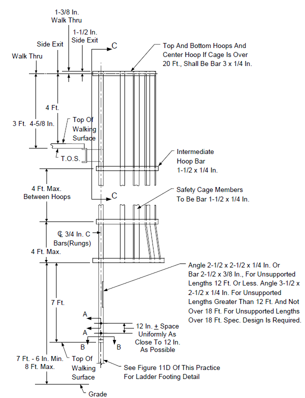
FIGURE 11B
LADDER AND CAGE DETAILS - PLAN VIEW
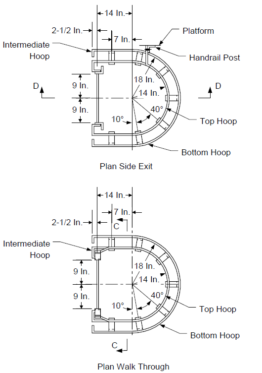
FIGURE 11C
LADDER AND CAGE DETAILS – SECTIONS
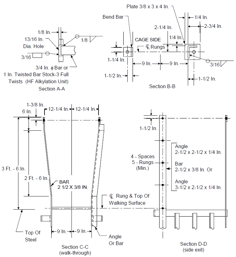
FIGURE 11D
LADDER AND CAGE DETAILS - FOOTING OR BASE DETAIL
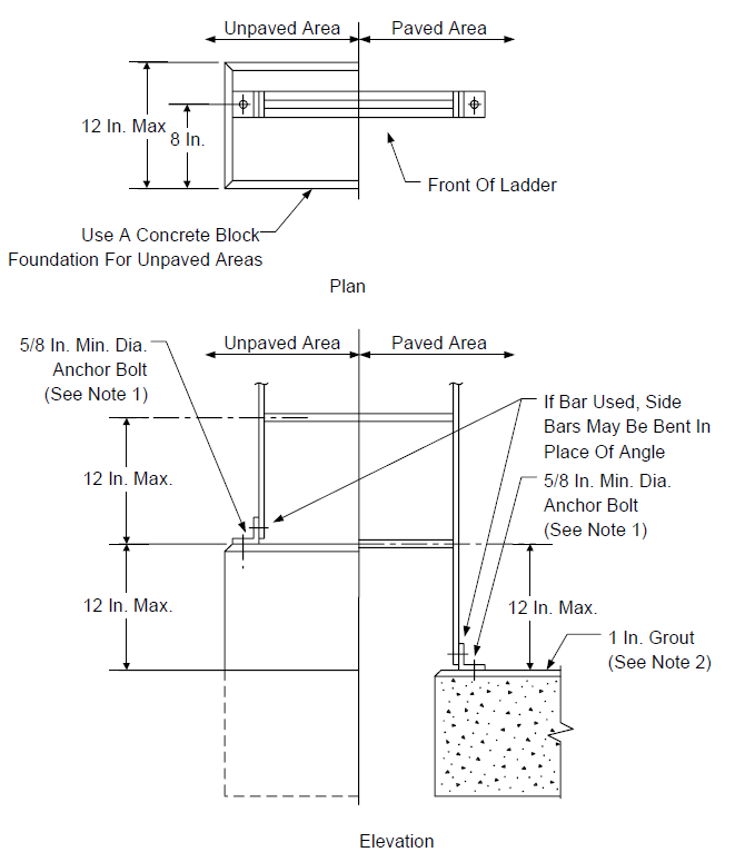
NOTES:
- Self drilling concrete anchor if existing footing.
- Grout shall be Type I per EP 4-2-9.
FIGURE 12 LADDER SAFETY GATE
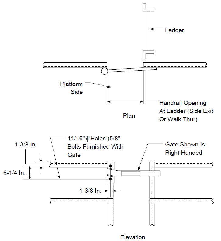
NOTES:
- Swinging gates shall have 2 bars, spaced approximately the distance between the upper and mid rails.
- (*) Safety gate shall be gravity loaded to return to closed position, unless otherwise specified.
- If a spring-loaded gate is used, the spring material shall be corrosion resistant.
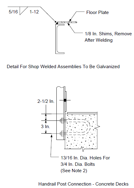
FIGURE 13A TYPICAL HANDRAIL DETAIL
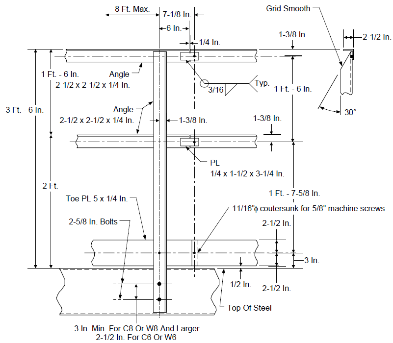
NOTES:
- Handrail connections shall be bolted or welded. Bolted connections require 5/8 in. diameter bolts. Stair treads require 3/8 in. diameter bolts. Handrail assemblies require 3/4 in. diameter bolts at connections to structure and stair stringers. welded connections shall be 3/16 in. fillet welds made all around.
- Holes in floor plate shall be 11/16 in. diameter countersunk for 5/8 in. diameter flat head machine screws on 18 in. centers. Holes shall be drilled by fabricator. Field drill and tap all supporting members
FIGURE 13B
REMOVABLE HANDRAIL SECTION DETAIL
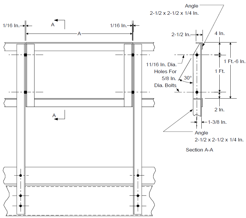
NOTES:
- (*) Dimension A to be specified by Owner's Engineer.
- Removable section to be shop assembled, welded or bolted. Bolted connections require 3/4 in. diameter bolts.
- See Figure 13A for other handrail details.
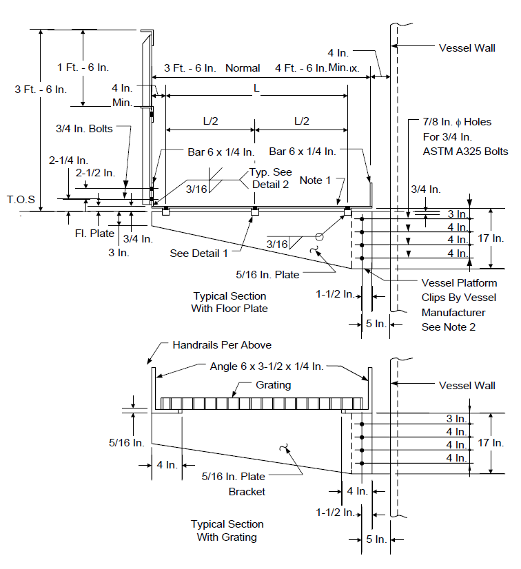
FIGURE 14A
TYPICAL HANDRAIL, FLOOR PLATE AND GRATING CONNECTIONS
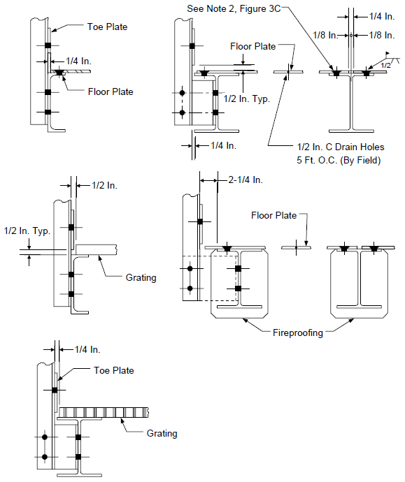
FIGURE 14B
TYPICAL HANDRAIL, FLOOR PLATE AND GRATING CONNECTIONS - CONTINUED
NOTES:
- (*) Other anchor bolt geometries shall be approved by the Owner's Engineer.
- Self drilling concrete anchors required for existing concrete.
FIGURE 15A
FLOOR GRATING ARRANGEMENT IN STRUCTURES - PLAN VIEW
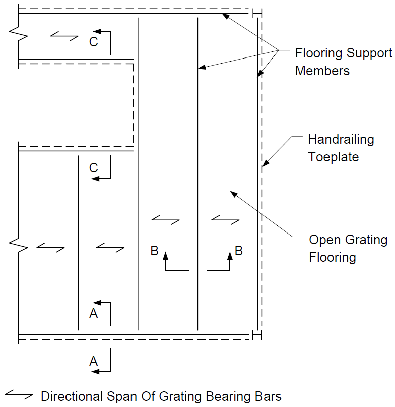
NOTES:
- Fixed floor grating is to be field attached to support members with 3/16 inch welds, 1 inch long on the terminal end of each tenth bearing bar.
- Floor grating specified to be removable on the design drawings is to be attached to support elements with mechanical fasteners to allow its removal and replacement.
- Except for removable sections, floor grating to be continuous over intermediate supports.
- Unless otherwise noted on the design drawings, flooring cutouts of less than 6 in. in diameter for piping and other penetrations shall be by the field.
- Flooring cutouts by the field of 10 in. diameter and greater for piping and other penetrations shall be protected and reinforced with a toe plate tack welded to floor grating as shown in Figure 15C.
FIGURE 15B
FLOOR GRATING ARRANGEMENT IN STRUCTURES - SECTIONS
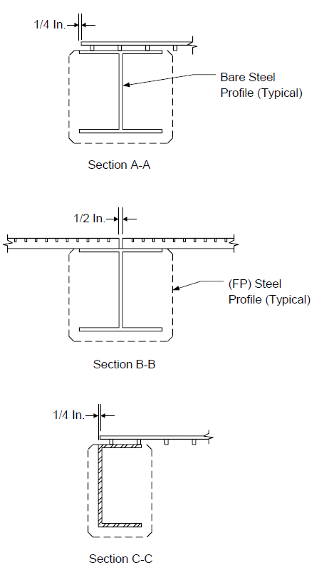
FIGURE 15C
FLOOR GRATING ARRANGEMENT IN STRUCTURES
- CUTOUT REINFORCEMENT
NOTE:
(1) Reinforcement is required for all 10-in. diameter and larger holes cut in grating.
FIGURE 16
STAIR DETAILS - GRADE TO PLATFORM
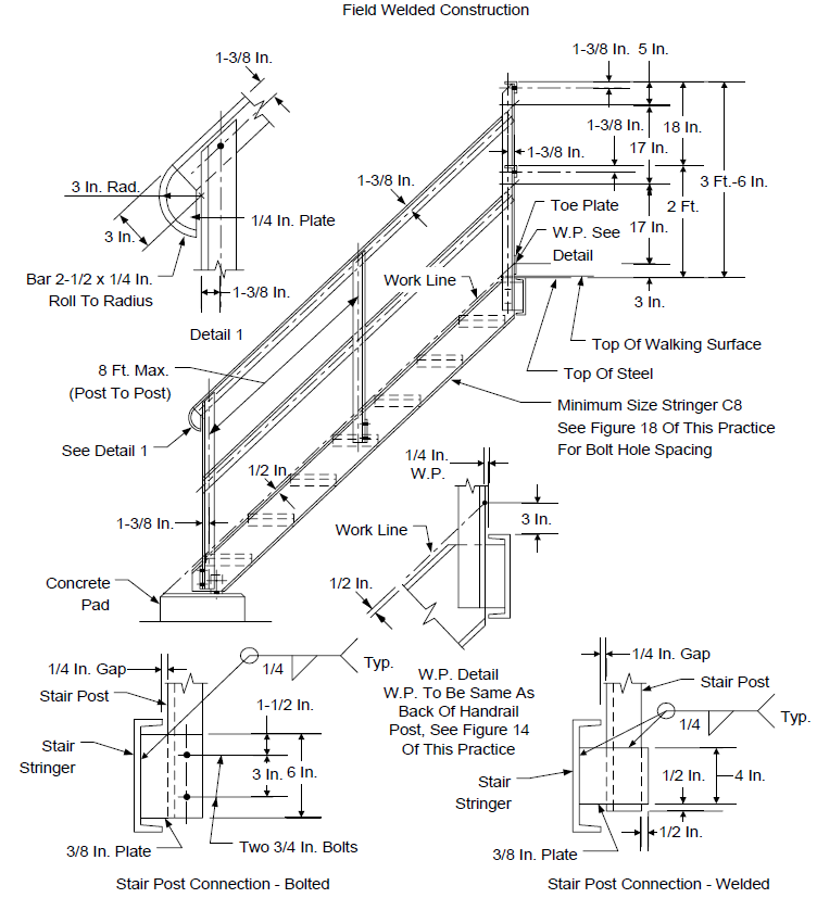
NOTE:
(1) All handrail, midrail and handrail posts shall be angle 2 1/2 x 2 1/2 x 1/4 in.
FIGURE 17
STAIR DETAILS - PLATFORM TO PLATFORM
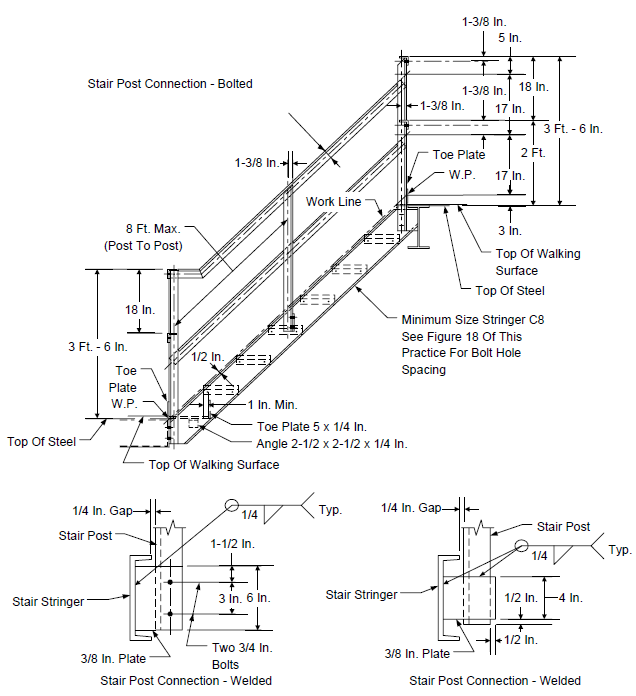
NOTE:
(1) All handrail, midrail and handrail posts shall be angle 2 1/2 x 2 1/2 x 1/4 in.
FIGURE 18
STAIR STRINGER DETAILS
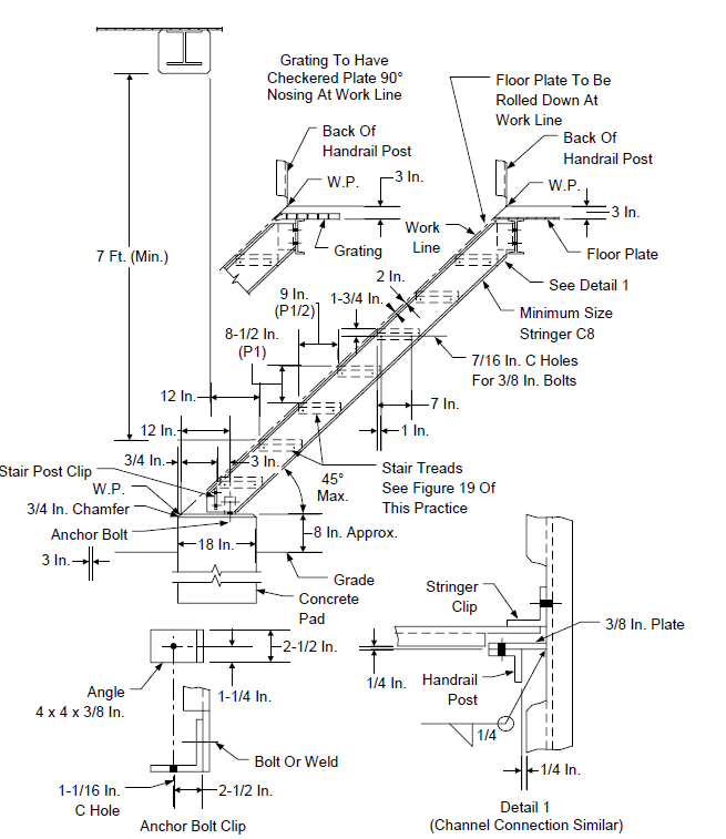
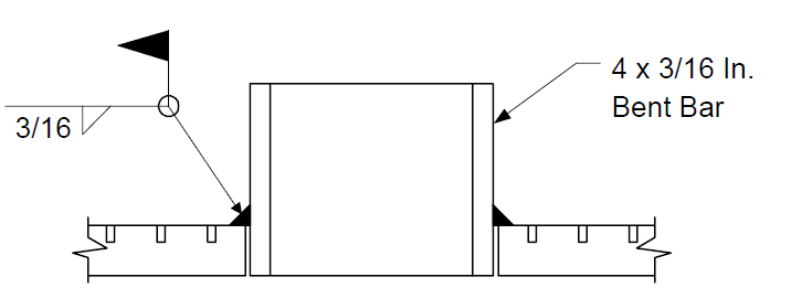
FIGURE 19 STAIR TREAD DETAIL
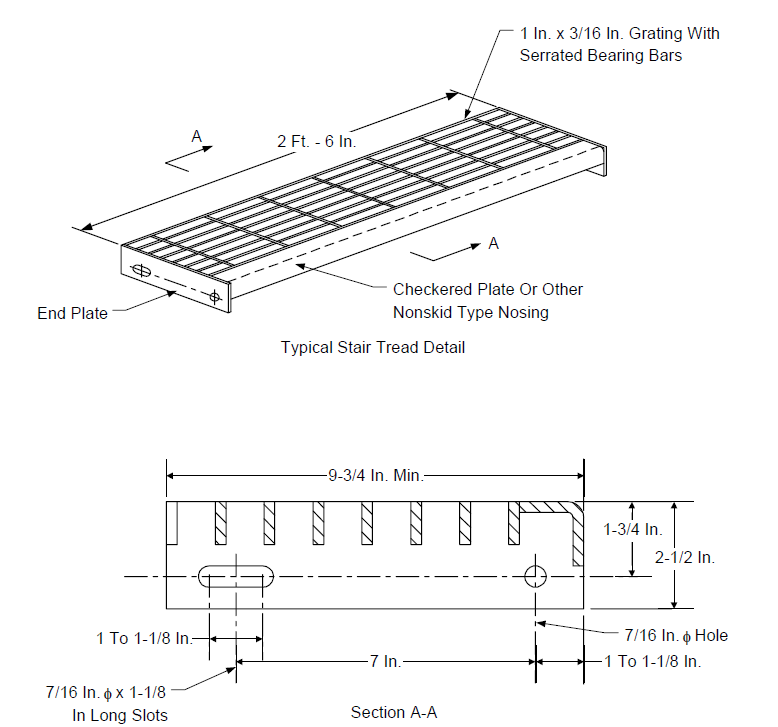
NOTES:
- All stair treads are to be hot dip galvanized in accordance with ASTM A123 after fabrication.
- Stair treads shall comply with OSHA requirements.
FIGURE 20A
WOODEN CROSSOVER – ELEVATION
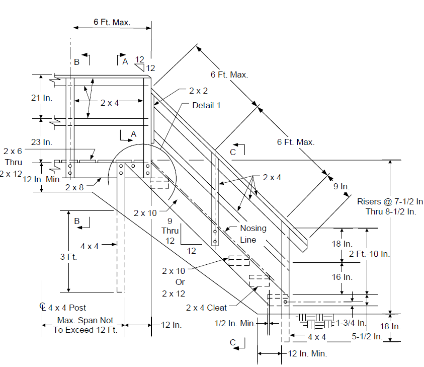
FIGURE 20B
WOODEN CROSSOVER - DETAIL AND SECTIONS
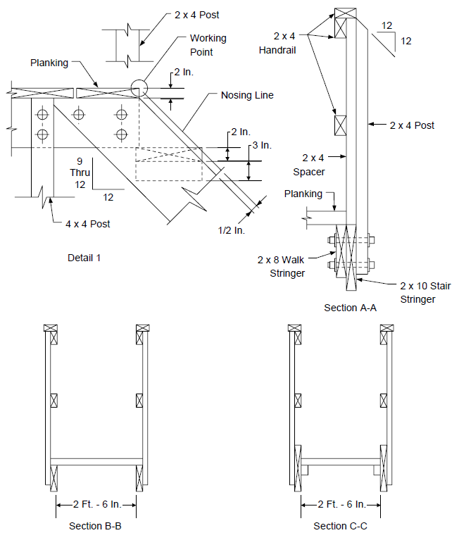
FIGURE 21 CONCRETE FIGURE
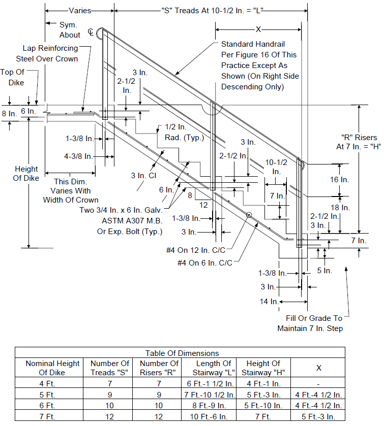
FIGURE 22A
STEEL CROSSOVER - ELEVATION
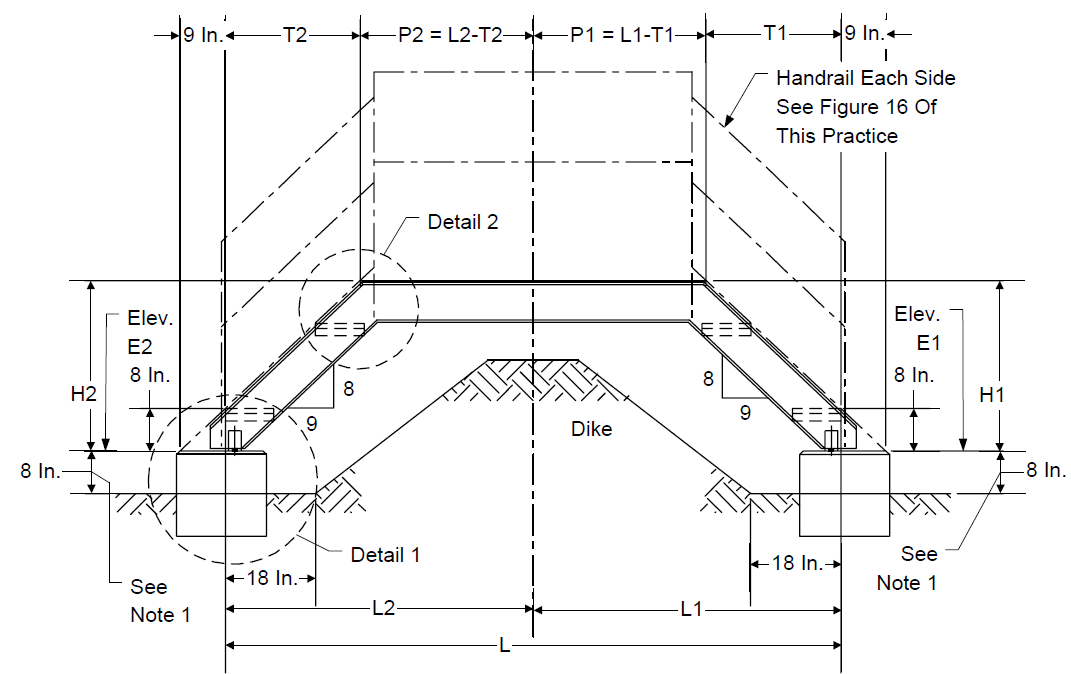
| Table 1 - Dimensions | Table 1 - Dimensions | Table 1 - Dimensions | Table 1 - Dimensions | Table 1 - Dimensions |
|---|---|---|---|---|
| Dike Height | H1 Or H2 | # Of Risers At 8 In. | T1 Or T2 | # Of Treads At 9 In. |
| 0 Ft. To 3 Ft.-6 In. | 4 Ft. | 6 | 3 Ft.-9 In. | 5 |
| 3 Ft.-6 In. To 4 Ft.-2 In. | 4 Ft.-8 In. | 7 | 4 Ft.-6 In. | 6 |
| 4 Ft.-2 In. To 4 Ft.-10 In. | 5 Ft.-4 In. | 8 | 5 Ft.-3 In. | 7 |
| 4 Ft.-10 In. To 5 Ft.-6 In. | 6 Ft. | 9 | 6 Ft. | 8 |
| 5 Ft.-6 In. To 6 Ft.-2 In. | 6 Ft.-8 In. | 10 | 6 Ft.-9 In. | 9 |
| 6 Ft.-2 In. To 6 Ft.-10 In. | 7 Ft.-4 In. | 11 | 7 Ft.-6 In. | 10 |
| 6 Ft.-10 In. To 7 Ft.-6 In. | 8 Ft. | 12 | 8 Ft.-3 In. | 11 |
| Table 2 - Dimensions | Table 2 - Dimensions |
|---|---|
| L | Stringer Size |
| 0 Ft. To 17 Ft. | C8 x 11.5 |
| 17 Ft. To 20 Ft. | C9 x 13.4 |
| 20 Ft. To 23 Ft. | C10 x 15.3 |
| 23 Ft. To 28 Ft. | C12 x 20.7 |
FIGURE 22B
STEEL CROSSOVER - PLAN AND DETAILSTANK LADDER FIGURE
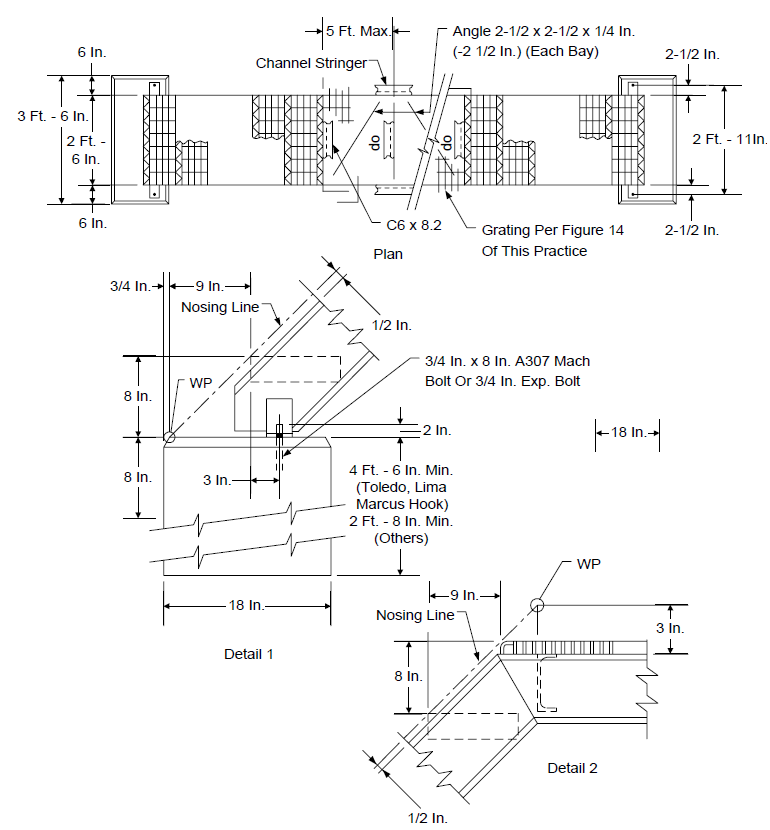
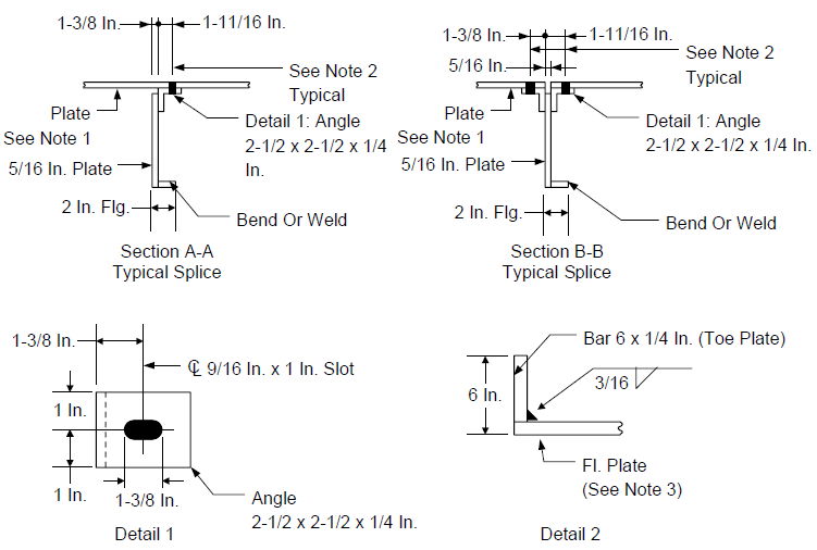
FIGURE 23
TANK LADDER DETAILS
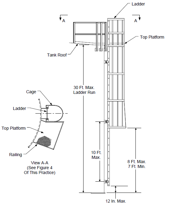
NOTES:
- Ladder and safety cage design shall be in accordance with this Practice.
- All ladders shall have side entrances to platforms or walkways.
FIGURE 24
RAILING AT FOAM CHAMBERS FOR FIXED ROOF FIGURE
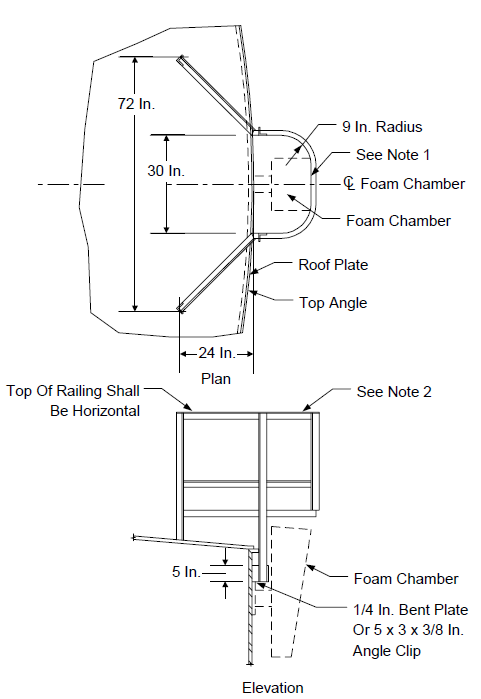
NOTES:
- The inside of the railing at the point indicated shall be directly above the outside edge of the foam chamber.
- The design of handrails shall be per Figure 13.
FIGURE 25
WING RAILING FOR FIXED ROOF FIGURE
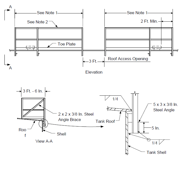
NOTES:
- Wing railing shall extend at least 7 feet on each side of roof access.
- The design of handrails shall be per Figure 13.
© 2026 Inflection Point Engineering, LLC. All rights reserved. The content of this page — including calculation methods, reference data, written analysis, interactive tools, and source code — is the intellectual property of Inflection Point Engineering, LLC and is protected under applicable copyright, trademark, and trade secret laws. Unauthorized reproduction, redistribution, modification, or derivative use in whole or in part is prohibited without prior written consent.
Disclaimer. This material is provided for informational and educational purposes only and does not constitute professional engineering advice. Calculations, reference data, and methodologies are based on published standards and accepted engineering practice but are not a substitute for engineering judgment, site-specific analysis, or review by a licensed Professional Engineer. Inflection Point Engineering, LLC makes no warranties, express or implied, regarding the accuracy, completeness, or fitness for a particular purpose of any content presented here, and shall not be liable for any direct, indirect, incidental, or consequential damages arising from its use. Users assume all risk associated with applying this content to real-world design, operations, or decisions.
© 2026 Inflection Point Engineering, LLC. All rights reserved.