 Section 4 — Structures and Foundations
Structural Steel Construction
IPE Engineering Practice IPE-EP-4-5-2
Document number: IPE-EP-4-5-2 · Section: 4 — Structures and Foundations
1.0 SCOPE 5
2.0 REFERENCES 5
3.0 DEFINITIONS 6
4.0 FOAM SYSTEM APPLICATIONS 8
4.1 Philosophy 8
4.2 Process Area Protection 9
4.3 Atmospheric Storage Tank Protection 9
4.4 Loading/Unloading Rack Protection 9
4.5 LNG Spill/Fire Protection 9
4.6 Pier and Wharf Protection 9
5.0 GENERAL DESIGN AND INSTALLATION REQUIREMENTS 9
5.1 Design and Installation Responsibility 9
5.2 Proposal Requirements 10
5.3 Design Development and Documentation 10
5.4 General Design Considerations 11
5.5 System Operation 14
5.6 Equipment Selection 14
5.7 Design Considerations for Specific Applications 15
6.0 PORTABLE AND MOBILE FOAM EQUIPMENT 16
6.1 Portable Foam Equipment 16
6.2 Mobile Foam Equipment 17
7.0 SUBSURFACE INJECTION SYSTEMS 17
8.0 FOAM CHAMBER SYSTEMS 18
8.1 Fixed Roof Tank Protection 18
8.2 Floating Roof Tank Protection 18
9.0 CATENARY SYSTEMS 19
9.1 Design 19
9.2 Installation 20
10.0 THROUGH–THE–TANK SYSTEMS 21
10.1 Design 21
10.2 Installation 21
11.0 TANK STANDPIPE SYSTEMS 21
11.1 Design 21
11.2 Installation 22
12.0 FOAM–WATER SPRAY SYSTEMS 22
12.1 Design 22
12.2 Installation 23
13.0 HIGH EXPANSION FOAM SYSTEMS 23
14.0 ACCEPTANCE TESTING 23
15.0 SYSTEM MAINTENANCE AND PERIODIC TESTING 23
15.1 General 23
15.2 Inspections 24
15.3 System Tests 24
15.4 Maintenance 24
16.0 TABLES 26
Table 1 Foam Requirements for Atmospheric Storage Tanks - Class I, II and IIIA Liquids 24
Table 2 Suitability of Types of Foam Concentrates 25
Table 3 Density, Water and Foam Concentrate Supply Requirements for Foam Systems 26
Table 4 Foam Requirements for Atmospheric Storage Tanks - Class I, II or IIIA Liquids 27
Table 5 Flush Flow Rates 28
Table 6 Piping Flushing Rates 28
Table 7 Documentation Requirements for Fire Protection from EP 3–5–4 28
17.0 FIGURES 29
Figure 1 Process Unit Spill Area Calculation (Ditch Drains) 29
Figure 2 Catenary Foam System 30
Figure 3 Through The Tank Foam System (Semifixed System). 31
Figure 4 Manual Protection – Foam Standpipe. 32
SCOPE
- This Practice covers the design requirements for manually and automatically activated foam fire protection systems provided as primary protection for flammable and combustible liquid storage, handling and processing areas at refining facilities. This Practice does not cover manual foam fire fighting techniques or emergency foam application techniques that may be employed if the primary foam protection system fails or the magnitude of the fire exceeds the capability of the primary foam protection system (e.g. sinking of a floating roof).
- Any deviation from this Practice must be approved by the procedures described in EP 1–1–3.
- An asterisk (*) indicates that a decision by the Owner or the Owner’s Engineer is required or that additional information is furnished by the Purchaser.
- Documentation required for fire protection systems constructed in accordance with this Practice is given in Table 7.
2.0 REFERENCES
The latest edition of the following standards and publications are referred to herein.
STANDARDS AND PUBLICATIONS
| Engineering Practices |
|---|
| EP 1–1–3 Deviations to Engineering Practices EP 2–5–2 Documentation Format Requirements EP 3–5–2 Firewater Systems EP 3–5–3 Fixed Water Spray Fire Protection Systems EP 3–5–6 Fire Protection of Piers and Wharves EP 5–1–1 General Piping Design EP 9–1–1 Atmospheric Storage Tanks EP 10–3–1 Shop Painting EP 10–3–2 Field Painting EP 10–3–3 Corrosion Protection for Underground Pipe EP 13–1–1 Power System Design Practices EP 14–1–1 Winterization |
| ASME/ANSI Standards |
| B1.1 Unified Inch Screw Threads B2.2 Dryseal Pipe Threads B16.5 Steel Pipe Flanges, Flanged Valves and Fittings |
| ASME Code |
| B31.3 Process Piping |
| API Publication |
| Publ 2021 Guide for Fighting Fires in and Around Flammable and Combustible Liquid Atmospheric Storage Tanks |
STANDARDS AND PUBLICATIONS (CONT.)
| NFPA Codes |
|---|
| 11 Low Expansion Foam and Combined Agent Systems 11A Medium and High Expansion Foam Systems 11C Mobile Foam Apparatus 16 Deluge Foam–Water Sprinkler and Spray Systems 30 Flammable and Combustible Liquids Code 72E Automatic Fire Detectors 321 Basic Classification of Flammable and Combustible Liquids 1961 Fire Hose |
| Military Specification |
| MIL–F–24385C Fire Extinguishing Agents Aqueous Film Forming (ASFF Liquid Concentrate Fresh and Seawater) |
DEFINITIONS
- Approved – Acceptable to the “authority having jurisdiction”.
- Aspirating Device – A device that introduces air into a foam solution to create fire fighting foam. Aspirating devices include foam nozzles, foam chambers, and high, medium and low back pressure foam makers.
- Authority Having Jurisdiction – The organization, office, or individual responsible for “approving” equipment, installations, and procedures.
- Automatic Detection – Equipment that will automatically detect heat, flame, smoke, flammable gases or other conditions which are likely to result in a fire or explosion and will automatically activate the alarm and protection systems.
- Combustible Liquid – Per NFPA 30, a liquid having flash point at or above 100ºF. Combustible liquids are subdivided as follows:
- Class II – Those liquids having flash points at or above 100ºF and below 140ºF.
- Class IIIA – Those liquids having flash points at or above 140ºF and below 200ºF.
- Class IIIB – Those liquids having flash points at or above 200ºF.
- Concentration – The percentage of foam concentrate contained in a foam solution. The required concentration will be dependent on the particular foam concentrate used.
- Discharge Device – A fixed, semi–fixed, mobile or portable device that directs the flow of foam to the fire or liquid surface. Discharge devices include foam chambers, foam–water sprinkler heads, and foam nozzles.
- Density – The unit rate of foam solution application to a liquid surface area, expressed in gallons per minute per square foot (gpm/ft2).
- Eductor (Inductor) – A device that uses the Venturi principle to introduce a proportioned quantity of foam concentrate into a water stream.
- Enclosed Process Area – An area containing process equipment located within a building or congested area, with restricted access such that manual firefighting would be hazardous or difficult, or the heat and smoke from a fire would not be readily dissipated.
- Expansion – The ratio of the final foam volume to the volume of the original foam solution before adding air. Foams are arbitrarily subdivided into three ranges of expansion:
- Fixed Roof Tank – A cone roof tank with or without an internal floating cover of any type.
- Flammable Liquids – Per NFPA 30, a liquid having a flash point below 100ºF and having a vapor pressure not exceeding 40 psia at 100ºF is known as a Class I liquid. Class I liquids are subdivided as follows:
- Class IA – Those liquids having flash points below 73ºF and having boiling points below 100ºF.
- Class IB – Those liquids having flash points below 73ºF and having boiling points at or below 100 ºF.
- Class IC – Those liquids having flash points at or above 73ºF and below 100ºF.
- Flash Point – The minimum temperature of a liquid at which sufficient vapor is given off to form an ignitable mixture with the air near the surface of the liquid or within the tank. The flash point shall be determined using the appropriate test in accordance with ASTM testing procedures as specified in NFPA 30.
- Foam – A stable aggregation of small bubbles having a lower density than oil or water that flows freely over a burning liquid surface and forms a tough continuous blanket to seal volatile combustible vapors from access to air. Foam is produced by mixing air into a solution of water and foam concentrate.
- Foam Concentrate – A concentrated liquid foaming agent as received from the Manufacturer. Foam concentrate is usually manufactured for use as 1%, 3% or 6% solution in water. Foam concentrates suitable for use in hydrocarbon processing facilities are:
- Fluoroprotein Foam Concentrates – consists primarily of protein–based compounds with additives to control viscosity, prevent corrosion and resist decomposition, plus a synthetic fluorinated surfactant that enhances resistance to oil pick–up and may form a vaporization preventing film on the surface of the liquid fuel.
- Aqueous Film Forming Foam (AFFF) – A foam that develops an aqueous film on a fuel surface which suppresses the evolution of fuel vapor. AFFF is most effective for control of hydrocarbon spill fires and is compatible with dry chemical extinguishing agents (see NFPA 11 for detailed description and system requirements).
- Film–Forming Fluoroprotein (FFFP) Foam Concentrates – A combination of Fluoroprotein and AFFF foams, with most of the advantages of each.
- Alcohol–Resistant Foam Concentrates – Used for fighting fires on water–soluble materials and other foam destructive materials.
- High Expansion Foam Concentrates – based on hydrocarbon surfactants, are used in specially designed equipment to produce foams with expansions in excess of 200:1. While these foam are inferior to fluoroprotein or AFFF concentrates for liquid hydrocarbon fire extinguishment, they are relatively effective for fire and vapor generation control of liquified natural gas (LNG).
- Foam Solution – A homogeneous mixture of water and foam concentrate in the proper concentrations.
- Foam System – A system consisting of an adequate water supply, foam concentrate supply, suitable proportioning equipment, distribution piping or hose, aspiring device(s) and discharge devices designed to adequately distribute foam over the hazard. Some foam systems also include detection devices. There are four basic types of foam systems:
- Fixed Systems – Complete installations piped from a central foam station, discharging through fixed delivery outlets to the hazard being protected. Any required pumps are permanently installed.
- Semifixed Systems – Systems that employ some fixed equipment and some portable equipment to effect foam delivery to the hazard. Generally, either the foam discharge outlets are fixed at the hazard location and supplied by portable or mobile proportioning equipment, or a fixed foam proportioning and distribution system is provided and portable equipment is used to deliver the foam to the hazard.
- Mobile Systems – Any foam producing unit which is mounted on wheels and either self propelled or capable of being towed by another vehicle.
- Portable Systems – Systems where the foam producing equipment and materials are transported by hand.
- Manufacturer – The recipient of a direct or indirect purchase order for materials and/or equipment. In this context, a direct order is one issued to a Manufacturer by a Contractor or the Owner. An indirect order is one issued to a Manufacturer by a vendor (recipient of a direct order) for materials, fabricated components, or subassemblies.
- O. S. & Y. Valves – Outside stem and yoke valves.
- Owner – Refining Company.
- Owner’s Engineer – A Refining Company appointed engineer.
- Premixed Foam Solution – A properly proportioned mixture of water and foam solution ready for immediate use.
- Proportioning – The continuous introduction of foam concentrate at the recommended concentration into the water stream to form foam solution.
- Proportioning Device – A device used for introducing foam concentrate into a water stream at the proper concentration to create foam solution. Proportioning devices include in–line eductors, inducting foam nozzles, foam pumps with metering valves, pressure proportioning (bladder) tanks, and coupled water–motor pumps.
FOAM SYSTEM APPLICATIONS
This Section of the Practice describes the basic philosophy behind foam fire protection and when foam fire protection systems are required. The requirements for foam fire protection systems shall also comply with all appropriate federal and local jurisdictional requirements. In case of conflicts, the more stringent requirement shall apply.
- Philosophy
- The objectives of installing foam fire protection systems are to provide for the life safety of personnel and to limit property damage. This is accomplished by:
- Extinguishing flammable and combustible liquid fires by excluding air from the surface of a burning liquid fuel and cooling the liquid.
- Preventing re–ignition of a liquid fuel by preventing volatile combustible vapors from combining with air.
- Preventing ignition of an un–ignited liquid fuel surface by suppressing the formation of combustible vapors from the liquid fuel surface.
- Foam fire protection systems are also designed and arranged to minimize firefighter exposure to the effects of hydrocarbon liquid fires or vapor clouds.
- Process Area Protection
- Mobile and/or portable foam fire protection equipment shall be used to protect open air process areas that store or handle flammable and combustible liquids.
- (*) Deluge foam–water spray systems shall be used to protect enclosed process areas where Class I liquids or Class II liquids are handled at any temperature, or Class III liquids are handled above their flash points. When adequate drainage is provided to an adequately sized containment area in a safe location, a water spray protection system may be installed in lieu of a deluge foam water spray system, with the approval of the Owner’s Engineer.
- Atmospheric Storage Tank Protection
- The type and extent of foam fire protection required for flammable and combustible liquid storage tanks depends on the characteristics of the tanks (type and size) and the liquid stored within them. Foam fire protection shall be provided for tanks storing Class I, II or IIIA liquids. Foam fire protection shall also be provided on tanks storing Class IIIB liquids that are heated to a temperature near or above their flash point.
- (*) Table 1 summarizes the foam fire protection requirements for storage tanks containing Class I, II or IIIA liquids based on the diameter and type of tank involved. The fire protection requirements for heated tanks containing Class IIIB liquids shall be evaluated on an individual basis through an engineering study submitted to the Owner’s Engineer for review.
- Loading/Unloading Rack Protection
A fixed foam–water spray system shall be installed on loading or unloading racks where Class I products are loaded or unloaded or where switch loading is practiced.
- LNG Spill/Fire Protection
A high–expansion foam system shall be installed in retention/vaporization areas of LNG storage facilities to reduce the rate of vaporization of spilled LNG and reduce the intensity of an LNG fire.
- Pier and Wharf Protection
Fixed ground level and elevated foam–water monitors and foam–water spray systems are used for the protection of piers and wharves where liquid hydrocarbons are handled. See EP 3–5–6 for a detailed discussion and recommendations for use of foam at these facilities.
GENERAL DESIGN AND INSTALLATION REQUIREMENTS
- Design and Installation Responsibility
- The design of foam fire protection systems shall be performed by persons fully experienced with foam system design and foam application requirements.
- The installation of fixed and semi–fixed foam and foam–water spray systems shall be performed by only those persons fully experienced in their installation.
- Proposal Requirements
- Each vendor’s proposal for a fixed or semi–fixed low expansion foam system shall included:
- Physical details of the hazard to be protected, including the location, arrangement and hazardous materials involved.
- The type, concentration, and available quantity of foam concentrate to be used in the system.
- The required solution application rate or density and duration.
- The locations, layout and spacing of the discharge devices.
- Water supply requirements.
- Descriptions and details (including materials used and overall dimensions) of:
- Piping and fittings,
- Foam proportioning equipment,
- Aspirating and discharge devices, and
- Any special accessories.
- Published literature providing a thorough explanation of the equipment, its operation, and its maintenance requirements.
- Manufacturer’s literature on the foam concentrate to be provided with the system, if applicable, including approvals and listings from testing laboratories.
- Description of actuating methods and devices.
- In addition, all proposals shall satisfy the requirements of the following NFPA standards as applicable:
- NFPA 11 – Low Expansion Foam and Combined Agent Systems
- NFPA 11A – Medium and High Expansion Foam Systems
- NFPA 16 – Deluge Foam–Water Sprinkler and Spray Systems
- Design Development and Documentation
The successful vendor shall perform a detailed system design and provide the following design documentation for review and approval prior to system installation:
- All information required for the system proposal.
- Design drawings that are scalable and easily reproducible that show:
- System layout and piping plans,
- Piping hanger and installation details,
- The location of proportioning devices, aspirating devices, discharge devices, foam concentrate storage facilities, and detection devices, and
- Schematic wiring diagrams.
- A complete set of hydraulic calculations, performed in accordance with the following NFPA standards as applicable:
- NFPA 11 – Low Expansion Foam and Combined Agent Systems
- NFPA 11A – Medium and High Expansion Foam Systems
- NFPA 16 – Deluge Foam–Water Sprinkler and Spray Systems
- General Design Considerations
- Foam Concentrate Selection
- Suitability:
- Table 2 indicates the suitability of the different types of foam concentrates for use in various hydrocarbon and polar solvent fire and spill situations. This table is based on the burn– back resistance, sealability, drain time, water stability and flowability of the different foam concentrates. These characteristics have a significant impact on the effectiveness of a given type of foam concentrate to control or extinguish a particular type of fire. This information shall be used to select the type of foam concentrate required for a particular foam system.
- AFFF concentrates shall comply with U.S. Military Specification MIL–F–24385C for compatibility.
- Approvals
Foam concentrates selected for use shall be listed by Underwriter’s Laboratory as a foam liquid concentrate, aqueous film forming foam liquid concentrate, or high expansion foam liquid concentrate as appropriate, and shall be used within the constraints of its listing.
- Density, Water Supply and Foam Concentrate Supply Requirements
- The density, water and foam concentrate supply requirements for foam systems are based on the hazard to be protected and the type of foam concentrate used. The appropriated density for foam systems protecting hydrocarbon liquids with up to 10 percent polar solvent content shall be as stated in Table 3. Table 3 also states the minimum duration for the water supply and foam concentrate supplies.
- The density of alcohol resistant foam required for protection of a foam destructive liquid hazard shall be based on the foam concentrate Manufacturer’s recommendation. The water and foam concentrate supply shall be adequate to produce the required quantity of alcohol resistant foam solution for at least 15 minutes for spill fire applications using portable equipment and at least 55 minutes for tank protection when fixed discharge devices are used.
- For fixed systems, the required quantity of foam concentrate shall be stored in the system foam concentrate storage tank. For semi–fixed systems and portable equipment, the required supply of foam concentrate shall be stored such that at least half of the required foam concentrate will be available for use within 5 minutes from the time of the fire alarm for process areas, and 20 minutes for storage tanks.
- Foam System Connections
Inlet connections shall be corrosion–resistant, provided with appropriate plugs or caps, and installed in accordance with the requirements in Table 3.
- Water Inlet Connections:
Water inlet connections shall not be provided on fixed foam systems or foam–water spray systems, unless required by the authority having jurisdiction (AHJ). If required by the AHJ, the water inlet connection shall be upstream of the proportioning equipment.
- Foam Solution Inlet Connection:
- A foam solution inlet connection shall be provided on foam solution lines from bladder proportioning tanks to allow the use of a secondary foam solution supply when foam concentrate in the bladder tank is depleted. A gate valve and check valve shall be provided on this connection. The connection shall be threaded with the standard thread of the refinery.
- A foam solution inlet connection shall be provided to allow mobile equipment to supply semi–fixed foam systems with fixed discharge devices. These connections shall be sized to ensure that the flow and pressure requirements of the system can be met and shall have at least two 2–1/2 inch female inlets, threaded with the standard thread of the refinery. The connections shall be located as follows:
- Uphill of the hazard being protected
- In the direction of, or perpendicular to, the predominant wind from the protected hazard
- Outside of the dike walls, containment curbs, or retention basins surrounding the protected hazard
- At least 50 feet from tanks less than 50 feet in diameter and one tank diameter from the shell of larger tanks
- Three to four feet above grade level
- Adjacent to a roadway
- Within 100 feet of fire hydrant
- Per the equipment and foam concentrate Manufacturers’ requirements
- The foam solution inlet connection for foam standpipes shall be located at the base of the tank at a height of 3 to 4 feet above grade level.
- Foam Concentrate Fill Connection:
A means shall be provided to allow atmospheric foam concentrate tanks to be refilled without interrupting foam production.
- Foam Solution Piping and Control Valves
- All piping shall be designed per EP 5–1–1.
- Steel pipe and all–welded construction shall be used for all foam solution lines on fixed and semi–fixed systems. The foam solution piping for foam–water spray systems shall meet the requirements of EP 3–5–3.
- (*) Threaded pipe fittings and flanged fittings may be used in the assembly of foam standpipes with the approval of the Owner’s Engineer. However, steel pipe with wall thicknesses less than schedule 30 for sizes NPS 8 inches and larger, or schedule 40 for sizes less than NPS 8 inches shall not be joined by threaded fittings.
- Threaded flanges and cast iron pipe fittings, valves, and strainers shall not be used.
- Pipe dope shall not be used because it tends to restrict water flow.
- Care shall be taken that the pipe does not extend into the fitting sufficiently to reduce the waterway. All pipe shall be reamed after cutting and/or threading to remove all burrs and fins. Whenever possible, the piping shall be located so that it does not hinder nor require disassembly during normal equipment maintenance.
- Foam solution piping shall be located above ground to minimize external corrosion and to allow the piping to be visually inspected. The piping shall be properly supported to prevent mechanical damage and sloped to allow for drainage.
- To prevent damage from fire exposure, the earth below the foam solution piping shall be graded so that the piping is at the high point within the dike wall or within 50 feet of a tank with no dike. This will prevent flammable liquid pools from collecting beneath the foam solution piping.
- Piping normally filled with liquid shall be protected from freezing when required by EP 14–1–1. This shall be accomplished by insulating and heat tracing the piping. If insulating and heat tracing of the piping is impractical, the piping shall be coated to prevent external corrosion and buried below the frost line.
- (*) Control valves for tank protection systems shall be located outside of the dike and not less than the following distance from the shell of the tank they serve: 50 feet for tanks less than 50 feet in diameter and a distance of one diameter for tanks 50 feet in diameter of larger. Control valves for fixed and semi–fixed foam systems protecting hazards other than tanks shall be located per the requirements for foam inlet connection listed in section 5.4.3 of this Practice. Control valves may be permitted at less than the above stated distances, if protected from fire exposure or remotely operated, and approved by the Owner.
- Foam System Flushing
- Before connecting the piping of a fixed system to the feed main, the underground piping and lead–in connections shall be flushed to remove foreign materials. Flushing shall continue until the water runs clear. The flushing flow rate shall equal the system demand or that necessary to produce a flow velocity to 10 ft/s, which ever is greater. Flow rates necessary to achieve a velocity of 10 ft/s are given in Table 5.
- (*) If the water supply will not produce the required flow, then the maximum available flow shall be used to flush the piping, if permitted by the Owner.
- Connection and Valve Labeling and Identification
- All water, foam concentrate, foam solution and foam connections, and all control valves on fixed systems shall be painted red (refer to the requirements of EP 10–3–1 and EP 10–3–2) and identified with permanently marked signs meeting the Owner’s standards or the following minimum criteria:
- A fixed system control valve shall be labeled “Foam System Control Valve”. The label shall also identify the tank or piece of equipment protected by the system.
- A water, foam concentrate, foam solution, or foam connection shall be labeled as to the type of connection (water foam concentrate, foam solution, or foam). The label shall also identify the piece(s) of equipment, area, or systems controlled by the valve.
- The sign shall have 1–1/2 inch (minimum) high white lettering on a red background.
- The signs may be painted onto the system piping or may be attached painted metal or fiberglass reinforced placards. If the identification sign is painted onto the piping it shall not encompass more than 1/2 of the pipe’s outer circumference. Plastic placards are not acceptable, unless they can be considered shatter proof under all expected weather conditions (particularly in freezing climates). In addition, embossed plastic tape, ink, crayon, and pencil are not acceptable.
- The placard shall be secured by bolting, chaining, or wiring (non–corrosive) the placard in place. The placard’s location shall not interfere with the valve’s operation.
- All identification signs shall face in the direction from which the firefighter(s) are expected to approach the valve.
- System Operation
- Fixed Systems
- Fixed foam and foam–water spray systems shall be manually actuated, unless one or more of the following conditions apply:
- The immediate control of the fire or spill is essential to prevent personnel injury, rapid fire growth or substantial equipment damage.
- The location is unattended or remote such that personnel cannot promptly activate the system manually upon fire ignition, or
- Conditions exist that would prevent personnel from reaching or using a manual actuation system.
- Combination UV/IR detection shall be used when immediate actuation of the system is required to prevent personnel injury. Line or spot type heat detectors shall be used when no significant life hazard is present.
- Automatic detection systems shall be designed, arranged and installed per NFPA 72E.
- The automatic detection equipment shall sound an alarm in the unit control room or other manned location upon actuation.
- Automatic detection and actuation equipment shall be provided with a 24 hour back up power supply. The loss of primary power shall not actuate the foam system.
- A means of manual actuation shall be provided on all automatically actuated systems.
5.5.2 Semi–fixed systems, mobile and portable equipment require varying amounts of manpower for set–up and operation. Installation of these systems or use of this equipment shall be limited to locations where adequate trained manpower is available. When the appropriate level of trained manpower is not available, a fixed system shall be provided.
- Equipment Selection
- General
Foam proportioning, aspirating, and discharge devices shall be designed for the intended use and listed by Underwriter’s Laboratory or approved by Factory Mutual.
- Foam Concentrate Storage Tanks
- Atmospheric tanks for storage of foam concentrates shall only be constructed of materials approved by the foam concentrate Manufacturer. Materials of construction for these tanks are normally mild steel or fiberglass reinforced polyester or epoxy. Steel tanks shall be designed with an expansion dome constructed of heavier gauge material than the tank shell to allow for internal corrosion. These tanks must be filled half way into the expansion dome. These tanks shall be closed to the atmosphere except for a pressure/vacuum vent mounted at the top of the tank.
- Under no conditions shall the interior of the tank be painted or lined.
- Design Considerations for Specific Applications
- Process Areas
Open air process units and other plant areas where flammable or combustible liquids are present shall be protected by mobile and/or portable foam equipment in accordance with this section.
- Basis for protection: Adequate portable and/or mobile foam equipment shall be provided for spill fire protection in the process areas. The design spill area for determining the amount of foam producing equipment required for process area protection shall be based on the largest of the following spill areas:
- The area covered by liquid when the inventory of the largest vessel containing Class I, II or IIIA liquids in a process unit leaks through the largest vessel connection below the liquid level and spills to grade. The following guidelines shall be used to estimate the design spill area in process units:
- In units provided with catch basins for drainage, the spill area shall be determined by the slope of grade in the area and arrangement and capacity of the catch basins. The minimum spill area shall be the two largest adjacent catch basin drainage areas in the unit.
- In units where all drainage is to drainage ditches at the periphery of the unit, the spill area shall be determined by the equation (NOTE: Figure 1 contains an example of this method.)
Aspill = D2 + Aditch, where: Aspill is the spill area
D is the distance between the center of the unit and the closest drainage ditch, and
Aditch is the area of the drainage ditch between the nearest fire seals.
- In substantially flat areas with little or no drainage, the spill area shall be based on 20 square feet per gallon of liquid contained in the largest vessel, up to a maximum area of 120 percent of the surface area of the unit.
- Where retention areas are provided with adequate capacity to hold at least 125% of the largest vessel inventory, the spill size shall be 120% of the largest retention area.
- The area of the largest API separator or waste water treating device that may be contaminated with liquid hydrocarbon in the event of an equipment or piping failure.
- The area of the largest cooling water retention area that could be contaminated with hydrocarbons in the event of an exchanger tube leak.
- Storage Tanks
- Table 4 summarizes the types of foam protection systems required for flammable and combustible liquid storage tanks. Foam protection systems for storage tanks shall comply with the requirements of NFPA 11 and the appropriate Section in this Practice.
- When adequate trained manpower is available, mobile and/or portable foam monitors shall be used for extinguishment of fires in cone roof tanks 60 feet in diameter or less and open top floating roof tanks less than 120 feet in diameter. When adequate trained manpower is not available, subsurface injection or a foam chamber system shall be used.
- Loading/Unloading Racks
Foam–water spray systems for loading and unloading racks shall be designed based on a spill covering an area extending 5 feet in all directions from the edge of the tank trucks or cars serviced by the rack. When drainage and/or containment is provided, the entire containment or drainage area for the rack shall be protected, if it exceeds the area required above. When no drainage or containment is provided, the spray shall be arranged to discharge over the area required above, but the application density and quantity of foam required shall be based on a spill area that extends 20 feet in all directions from the edge of the tank trucks or cars serviced by the rack.
PORTABLE AND MOBILE FOAM EQUIPMENT
- Portable Foam Equipment
Portable foam equipment shall comply with the requirements of NFPA 11 and the requirements of this Section.
- Handlines and Nozzles
- The minimum discharge rate for foam handlines and nozzles shall be 50 gallons per minute at 100 psi inlet pressure.
- Foam nozzles shall be listed by Underwriter’s Laboratory or approved by Factory Mutual.
- Aspirating foam nozzles shall be used for foam application. Nozzles shall have a minimum range of 75 feet in still air at an inlet pressure of 100 psi. Tests verifying nozzle range shall be performed, with documentation of the test results available on request.
- Lined single or double–jacketed fire hose shall be used for water and foam solution. The hose shall be rated for 300 psig service pressure, 600 psig proof test pressure.
- At least 300 feet of hose shall be provided for each foam nozzle. The hose diameter shall be at least 1–1/2 inches. The hose shall be adequate to supply the rated nozzle flow at 150 psi inlet pressure with a friction loss of less than 5 psi per 100 feet.
- When in–line eductors are used for foam proportioning, each eductor shall be sized to match the rate flow of the nozzle for which it is intended. Compatible nozzles and eductors shall be clearly labelled, color coded, or otherwise marked to ensure that proper nozzle/eductor combinations can easily be selected.
- Foam Monitors
Foam monitors shall meet the requirements of NFPA 11 and the requirements of this Section.
- Foam monitors may be portable, wheeled, trailer–mounted, or mounted on a mobile foam apparatus. When used to meet the required foam density for process area protection, no more than 50 percent of the foam flow shall be from apparatus or trailer–mounted monitors.
- Monitors shall be provided with aspirating nozzles rated in accordance with the monitor design. Nozzles shall have a minimum range of 150 feet in still air at an inlet pressure of 100 psi. Tests verifying nozzle range shall be performed, with documentation of the test results available on request.
- An adequate quantity of hose shall be provided to locate the monitor at least 200 feet from a water source (hydrant or pumper). The diameter and number of supply lines shall be adequate to supply a water flow rate equal to the flow rate of the nozzle at 150 psi inlet pressure with a friction loss of 10 psi/100 feet or less. The minimum hose diameter shall be 2–1/2 inches. The type, size and number of hose connections on the monitor shall be compatible with the hose couplings to be used and the number of supply lines required.
- Lined single or double–jacketed fire hose shall be used for water and foam solution. The hose shall be rated for 300 psig service pressure, 600 psig proof test pressure.
6.2 Mobile Foam Equipment
Mobile foam equipment shall meet the requirements of NFPA 11C.
SUBSURFACE INJECTION SYSTEMS
- Subsurface foam injection shall be designed and installed in accordance with NFPA 11. They shall utilize a fluoroprotein foam solution. The 3 percent liquid concentrate should be proportioned at 4 percent for good sub–surface results. Optimum foam characteristics for sub– surface injection purposes are 2 to 4 expansion with a 25 percent drainage time of 90 to 180 seconds.
- Only an Underwriter’s Laboratory listed or Factory Mutual approved high back pressure foam maker shall be used to generate foam for sub–surface injection. The foam makers shall be designed to provide foams with optimum characteristics for sub–surface injection against back pressures up to 40 percent of the inlet pressure.
- High Back Pressure foam makers shall be designed to perform satisfactorily at inlet pressures of 100 to 300 psig, provided the system is designed so that back pressure does not exceed 40 percent of the inlet pressure at the desired flowrate.
- Depending on tank sizes, more than one foam maker may be required for injecting foam into larger tanks. The foam makers shall be selected so that a minimum number is needed to provide the required foam flow for the largest tank, while limiting the size and weight so that they can be easily handled and mounted on a fire truck. On smaller tanks, an oversized high back pressure foam maker may be used as long as the foam solution rate does not exceed 0.3 US gpm/ft2, three times the recommended minimum rate.
- The supply of foam liquid concentrate available for subsurface injection shall be the sum of the quantities defined in the following items:
- Storage Tanks: The supply of foam liquid concentrate shall be sufficient to permit operation at the delivery rates specified in Table 3 for the minimum periods of time listed in Table 3.
- Foam Hose Streams: The minimum number of hose streams required as supplementary protection to extinguish small ground fires shall be provided as specified in NFPA 11, Chapter 3. Each hose stream shall have a minimum solution rate of 50 gpm. Adjustment of the minimum operating time may be made when streams of greater capacity are provided. Additional foam liquid concentrate shall be provided to permit operation of the hose streams with the tank foam installation.
FOAM CHAMBER SYSTEMS
Foam chamber systems shall be installed for storage tank protection as indicated in Table 4. The systems shall be designed to provide the density of fluoroprotein foam required in Table 3 to the protected area for the time stated in Table 3. In addition, adequate foam supplies and foam producing equipment shall be provided to support supplemental foam hose streams, as specified in NFPA 11, Chapter 3.
- Fixed Roof Tank Protection
- Design
- Each foam chamber shall be provided with a separate foam feed main and control valve.
- For semi–fixed systems, the foam feed mains for all foam chambers protecting an individual tank shall be routed to a single location outside the dike wall to allow supply of all foam chambers from a single foam fire truck. The piping shall terminate in a foam solution inlet connection as described in Section 5.4.3.2.2 of this Practice. The control valve shall be located immediately downstream of the foam solution connection, outside of the dike wall.
- For fixed systems, the foam feed mains shall terminate at the foam supply piping. The control valve shall be located immediately downstream of the connection to the foam supply piping, outside the diked area.
- Installation
In order to protect the foam solution piping from the upward force and shock of a tank roof rupture one of the following methods shall be used:
- When buried pipe is used, a swing joint shall be provided at the base of each tank. The swing joint shall use standard weight steel fittings.
- When above ground piping is used it shall not be held down within a distance of 50 feet from the tank shell to provide flexibility in the upward direction and to eliminate the need for a swing joint. Any threaded connections within this distance shall be back welded.
- When tank risers use NPS 4 inch or larger piping, they may be welded to the tank by means of a steel brace plates. Each brace plate shall be perpendicular to the tank shell and centered along the center of the riser. One brace plate shall be provided at each tank course. This design allows swivel joints and above ground piping flexibility to be eliminated.
- One flanged joint shall be provided on each riser. This joint shall be immediately upstream of the foam chamber to allow it to be easily replaced and to permit hydrostatic testing of the piping upstream of the foam chamber.
- Floating Roof Tank Protection
- Design
- A single foam feed main with control valve shall be provided for each protected tank, with branch risers supplying the individual foam chambers.
- For semi–fixed systems, the foam feed main shall be routed to a safe location outside the dike wall to allow supply of all foam chambers from a single foam fire truck. The piping shall terminate in a foam solution inlet connection as described in Section 5.4.3.2.2 of this Practice. The control valve shall be located immediately downstream of the foam solution connection, outside of the dike wall.
- For fixed systems, the foam feed main shall terminate at the foam supply piping. The control valve shall be located immediately downstream of the connection to the foam supply piping, outside the diked area.
- Installation
- (*) The foam discharge outlets shall be positioned above the highest elevation of the tank roof through the use of baffle plates, unless otherwise approved by the Owner’s Engineer. The baffle plates shall be centered on the foam discharge outlets, be a minimum of 3 feet high and extend at least 1 foot above the foam discharge outlets.
- One flanged joint shall be provided on each riser. This joint shall be immediately upstream of the foam chamber to allow it to be easily replaced and to permit hydrostatic testing of the piping upstream of the foam chamber.
- Tank riser piping shall be suitably attached to the tank to minimize piping movement and to support the weight of the piping and foam solution.
- A foam dam shall be provided and installed per NFPA 11, and EP 9–1–1.
CATENARY SYSTEMS
- Design
- Catenary systems shall be designed to deliver the required foam density. The design of catenary systems shall be in accordance with NFPA 11, except that two foam makers should be provided on each catenary foam system. One foam maker shall be provided on each side of the catenary hose tee on the foam ring (See Figure 2). If two foam makers cannot meet the foam demand, a foam maker shall be provided at each foam discharge outlet. However, the two foam maker design is preferred since it allows foam makers with larger solution orifices to be used, reducing the probability of clogging. It also reduces maintenance requirements, reducing the time that personnel must spend on the tank roof; and it reduces the probability of a foam maker being damaged by a seal fire.Figure 2)
- A length of stainless steel braided hose shall be installed between the ladder pipe and the swivel joint to span the width of the seal area. The swivel joint shall be on center with the ladder hinges or swivel rod to minimize stress on the piping and braided hose. The ladder piping shall be provided with an automatic drain, minimum orifice size 1/2 inch, at the low point of the bottom elbow.
- (*) Strainers shall not be used on the inlets of the foam makers in order to minimize the possibility of clogging, unless otherwise approved by the Owner’s Engineer. The air inlets of the foam makers shall be arranged to prevent rain and debris from falling into them and to prevent blockage by snow. When the foam discharge outlets penetrate the primary and secondary tank seals, the discharge outlets of the foam makers shall be provided with frangible seals to prevent vapors from entering them.
- The catenary hose shall be of hard rubber construction with carbon steel wire braid to protect it against weathering and abrasion. The selected hose shall also have a high resistance to ultraviolet light and chemical degradation. Fabric fire hose is not acceptable for this application. The length of the catenary hose shall be chosen so that it is fully extended when the tank roof is at its lowest elevation to prevent possible entanglement with roof fixtures.
- A single foam feed main with control valve shall be provided for each protected tank. For semi– fixed systems, the foam feed main shall be routed to a safe location outside the dike wall to allow the system to be supplied from a single foam fire truck. The piping shall terminate in a foam solution inlet connection as described in Section 5.4.3.2.2 of this Practice. The control valve shall be located immediately downstream of the foam solution connection, outside of the dike wall.
- For fixed systems, the foam feed main shall terminate at the foam supply piping. The control valve shall be located immediately downstream of the connection to the foam supply piping, outside the diked area.
- Before installing a catenary foam system onto an existing or new floating roof tank, an engineering evaluation shall be made to ensure that the additional weight of the ladder piping, catenary hoses, foam ring, foam makers, foam discharge outlets, foam dam (if provided) and foam will not upset the buoyancy of the floating roof. All piping and equipment shall be considered full of foam solution for this evaluation.
- Foam dams shall be installed on tanks equipped with tube seals and metal weather seals or non–combustible secondary seals.
- Installation
- Tank riser piping shall be suitably attached to the tank to minimize piping movement and to support the weight of the piping and foam solution.
- The ladder piping shall be securely attached to the bottom or side of the tank roof ladder and be properly aligned with the outlet of the swivel joint.
- The roof–mounted piping shall be arranged to form a complete foam ring along the periphery of the floating roof. It shall also be secured to the roof to prevent mechanical injury and arranged so that the catenary hose and the foam ring drain freely into the seal area. The self draining design is necessary to prevent liquid from accumulating within the piping or hose, and possibly freezing, and also to eliminate the need for personnel to descend onto the tank roof after a rim fire has occurred.
- When discharge outlets pass through a primary or secondary seal, a flexible seal shall be fitted between the discharge outlet and the edge of the opening.
- Foam dams, when required, shall be provided and installed per NFPA 11 and EP 9–1–1.
THROUGH–THE–TANK SYSTEMS
- Design
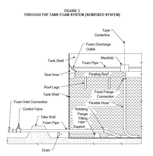
- Through–the–tank foam systems shall be arranged as shown in Figure 3. The through–the– tank foam system shall utilize a high pressure foam maker (carried by mobile equipment for semi–fixed systems) located outside of the dike wall. This foam maker shall supply a foam pipe that passes through the shell of the tank, just above grade level, terminating near the center of the tank floor. This foam piping shall be connected to a flexible pipe with a rotating flanged fitting. The flexible pipe then connects to a fixed flange connection near the center of the roof that is connected to a manifold on top of the floating roof. From the manifold, piping will radiate out to each foam discharge outlet.
- The flexible pipe shall consist of a spiral–wound stainless steel carcass with a thermoplastic outer sheath. The outer sheath shall be resistant to attack from the tank contents and foam solution. The flexible pipe shall resist kinking and have a repeatable lay pattern, as manufactured by Coflexip or equivalent. The Manufacturer of the flexible piping shall be consulted to determine the proper length of the flexible pipe in order to prevent possible entanglement with the roof legs.
- A control valve shall be provided for each system. For semi-fixed systems, the control valve shall be located immediately downstream of the foam pipe connection, outside of the dike wall. For fixed systems, the control valve shall be located immediately downstream of the high back pressure foam maker, outside the diked area.
- Before installing a through–the–tank foam system onto an existing or new floating roof tank, an engineering evaluation shall be made to ensure that the additional weight of the tank line, piping, foam makers, foam discharge outlets, foam dam (if provided) and foam will not upset the buoyancy of the floating roof. All piping and equipment shall be considered full of foam solution for this evaluation.
- Installation
- The manifold and roof mounted piping shall be arranged to drain into the seal area to prevent liquid from accumulating within the piping, and possibly freezing, and also to eliminate the need for personnel to descend onto the tank roof after a rim fire has occurred.
- The flexible pipe and solution piping shall be arranged to drain to a normally closed low point drain located within the dike wall. This low point drain shall be provided with an O.S. & Y type valve with a minimum size of 3/4 inch.
- When discharge outlets pass through a primary or secondary seal, a flexible seal shall be fitted between the discharge outlet and the edge of the opening. A blowout plug shall also be provided within the manifold to prevent vapors from entering the piping below it.
- Foam dams, when required, shall be provided and installed per NFPA 11 and EP 9–1–1.
TANK STANDPIPE SYSTEMS
- Design
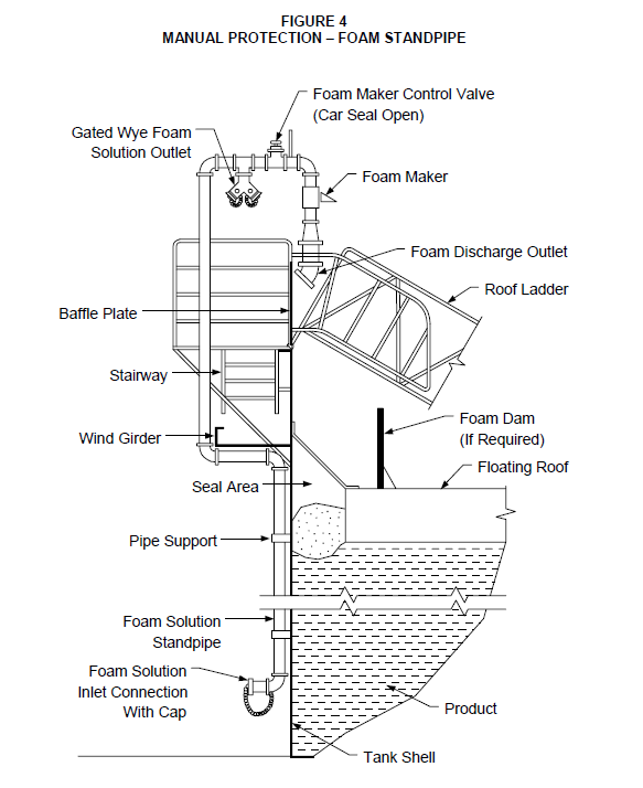
- Tank standpipes for the manual protection of floating roof storage tanks shall be arranged in accordance with Figure 4. They shall be sized to provide 150 gpm of foam solution at a pressure adequate to operate two foam handlines. Each handline shall be 200 feet long or the equivalent of half of the tank’s circumference, whichever is smaller. Each handline shall have an aspirating foam nozzle rated for 60 to 75 gpm. The hose shall be lined single jacket hose meeting the requirements of NFPA 1961. The hose and nozzles shall be stored in a protected enclosure or on mobile equipment.
- The control valve for the foam discharge outlet shall be a 1/4 turn ball valve (car sealed open) with a non–removable handle.
- The wye foam connection shall have two 1–1/2 inch gate valves. The threaded connections on the gate valves shall be compatible with the refinery’s standard fire hose thread. The wye fitting shall be permanently mounted with the gate valves in the normally closed position.
- Foam dams shall be installed on tanks equipped with tube seals and metal weather seals or non–combustible secondary seals.
- Access to the inlet connection shall be along the high point of the grade level within the dike enclosure.
- Installation
- The foam discharge outlet shall be positioned above the highest elevation of the tank roof and in an area with no obstructions. A baffle plate shall be provided in conjunction with the foam discharge outlet. The baffle plate shall be centered on the foam discharge outlet and shall be a minimum of 3 feet high and extend at least 1 foot above the foam discharge outlet.
- The foam maker control valve shall be located no higher than 5 feet above the stairway platform with the handle facing the direction from which the operator is expected to approach the valve.
- The wye foam connection shall be located no higher than 5 feet above the stairway platform with the handles facing the direction from which the operator is expected to approach the wye fitting. The wye fitting shall be permanently mounted with the gate valves in the normally closed position.
- Foam dams, when required, shall be provided and installed per NFPA 11 and EP 9–1–1.
- A strainer shall not be used on the inlet of the foam maker in order to minimize the possibility of clogging. The air inlet of the foam makers shall be arranged to prevent rain and debris from falling into it.
- The standpipe shall be suitably attached to the tank to minimize piping movement and to support the weight of the piping and foam solution. The standpipe shall be supplied through a foam inlet connection located at the base of the tank.
FOAM–WATER SPRAY SYSTEMS
- Design
Fixed foam–water spray systems provided for protection of loading/unloading racks or enclosed process areas shall be designed in accordance with the requirements of NFPA 16 and NFPA
11. For loading/unloading racks, the required discharge density and duration shall be in accordance with Table 3. The system shall be arranged to shut down all loading/unloading pumps and valves to the affected rack.
- Installation
Foam–water spray systems shall be installed in accordance with NFPA 16 and the EP 3–5–3.
HIGH EXPANSION FOAM SYSTEMS
The following design criteria shall be used for high expansion foam protection of LNG spill retention basins, pump pits, and other confined areas where leakage of LNG may occur in LNG storage facilities:
- The high expansion foam liquid concentrate and foam generators shall be listed by Underwriter’s Laboratory or approved by Factory Mutual.
- The high expansion foam produced by the generators shall have an expansion ratio of 500:1 and a quarter drainage time of at least 40 minutes.
- The foam application rate shall be between 20 and 25 cfm/ft2.
- Generators shall be located to maximize the delivery of high expansion foam to the area under prevailing wind conditions.
- The quantity of foam concentrate and water required shall be determined based on the required density of foam to cover the spill area and the time required for the LNG to vaporize.
ACCEPTANCE TESTING
- The installing Contractor shall provide 48 hours notice to the Owner before conducting the acceptance tests. This is to allow an Owner’s representative and any other concerned agencies to witness the test. The Owner will notify the Contractor if any representative will be witnessing the tests.
- Prior to final acceptance, the installing Contractor shall furnish a written statement that all aspects of the acceptance tests were successfully completed. Acceptance testing procedures shall be conducted in accordance with NFPA 16 for foam–water spray systems and NFPA 11 for fixed, semi–fixed, and standpipe systems. These tests include requirements for the flushing of piping, hydrostatic tests, inspection and visual examination of system components, foam discharge tests and operating tests of equipment and actuating systems.
- In addition, all underground piping shall be coated and cathodically protected in accordance with EP 10–3–3.
SYSTEM MAINTENANCE AND PERIODIC TESTING
- General
- The effectiveness of foam fire protection systems and equipment is highly dependent upon a sound maintenance and inspection program. Often experience shows that system and equipment maintenance is performed only when obviously impaired. Preventative maintenance and inspection is more effective in preventing system impairments and equipment failures. Key factors in a sound maintenance and testing program include proper design, full testing before placing the equipment in service, routine visual inspections and annual preventative maintenance.
- Testing, inspection and maintenance shall incorporate a review of all systems and subsystems to assure operability.
- Inspections
Inspections of fixed, semi–fixed, portable and mobile foam systems to detect obvious conditions affecting system effectiveness are recommended on a daily, weekly, and annual basis. Each recommended inspection routine has specific objectives to determine if the system is in operating readiness.
- Visual Inspections are required at various intervals to maintain effective operational capability. Operator routines shall include weekly visual checks of fixed systems and biannual checks of semi–fixed, portable, and mobile systems.
- Proper drainage of piping shall be verified each fall to prevent winter freeze–ups and to prevent corrosion.
- System Tests
Routine tests during the life of the system shall be compared with results during acceptance tests to gauge potential deterioration of system performance and operability. Annual tests provide assurance that actuating systems will operate when required.
- Automatic and remote–manual control valves shall be tested as a minimum requirement. This test shall actuate the valve, but may not require flow of foam from the system. The manual control valve can be closed or partially closed to restrict system flow. When the remote controlled system valve is tripped, the valve can be completely closed. However, a full operational test (see below) with foam flowing is the best method to determine that the system will operate properly. Remote–manual control valves shall be tested separately from each actuation point.
- Every 3 years, a full flow test of each system shall be conducted. Flow tests shall be made more frequently, if conditions warrant.
- Maintenance
Properly performed annual maintenance is required to prevent failures of the systems during emergencies. The following annual maintenance sEPs shall be followed:
- Manual tripping devices and valves, including outside screw and yoke (OS&Y) valves and post indicator valves shall be operated. This involves completely closing and opening the valves. When opening valves, the handle shall be turned until resistance is felt in the operating rod, thus assuring that the rod has not become detached from the valve gate. The handle shall be backed a quarter turn from the fully open position to prevent jamming.
- All valve stems shall be lubricated. Graphite or graphite in light oil shall be applied to the valve stem. The valve shall be opened and closed to distribute the lubricant.
- The underground lead–in connections to fixed system risers shall be flushed. The flushing operation shall be continued long enough to ensure thorough cleaning. The minimum rate of flow shall not be less than the system demand as determined by the system design, or not less than the flow necessary to provide a velocity of 10 ft/s (3 m/s), whichever is greater.
- The flow rate required to produce a velocity of 10 ft/s is given in Table 6.
16.0 TABLES
TABLE 1
FOAM REQUIREMENTS FOR ATMOSPHERIC STORAGE TANKS - CLASS I, II AND IIIA LIQUIDS
| Tank Type | Tank Diameter | Foam Protection Requirements |
|---|---|---|
| Cone Roof | 60 feet or less | Portable and/or mobile equipment for full tank surface area. |
| Cone Roof | > 60 Feet | Fixed or semi–fixed system designed for full tank surface area. |
| Cone Roof with Metal Pan Type Cover (1) |
All | Fixed or semi–fixed system for protection of the full tank surface area. |
| Cone Roof with combustible cover (1) |
All | Fixed or semi–fixed system for protection of the full tank surface area. |
| Cone roof with thin steel skin cover on floats |
All | None required, unless by local code. If required, provide a fixed or semi–fixed system for rim seal protection. |
| Cone roof with thin skin aluminum cover on floats or aluminum honeycomb cover |
All | None required, unless by local code. If required, provide a fixed or semi–fixed system or full surface protection. |
| Floating Roof | < 100 Feet | Portable and/or mobile equipment for rim seal protection. |
| Floating Roof | 100–120 Feet | Portable and mobile or fixed equipment for rim seal protection. |
| Floating Roof | > 120 Feet | Fixed or semi–fixed system for rim seal protection. |
| Covered Floating Roof | All | None required, unless by local code. If required, provide a fixed or semi–fixed system for rim seal protection. |
NOTE:
(1) This design is not permitted by NPFA 30 and should not be considered for new installations
TABLE 2
SUITABILITY OF TYPES OF FOAM CONCENTRATES
| Fire/Spill Situation | Type of Foam Concentrate | Type of Foam Concentrate | Type of Foam Concentrate | Type of Foam Concentrate | Type of Foam Concentrate |
|---|---|---|---|---|---|
| Fire/Spill Situation | Fluoroprotein | AFFF | FFFP | Alcohol Resistant | High Expansion |
| Process Area Spill Fire | A | P | A | P | N.S. |
| Storage tank fire – Surface application (up to 10% polar solvent content) |
P | N.S. | N.S. | A | N.S. |
| Storage tank fire – Subsurface Application (up to 10% polar solvent content) | P | N.S. | N.S. | N.S. | N.S. |
| Storage tank fire – Surface Application (> 10% polar solvent content) | N.S. | N.S. | N.S. | P | N.S. |
| Storage tank - Subsurface Application (> 10% polar solvent content) |
N.S. | N.S. | N.S. | N.S. | N.S. |
| Loading rack fire – (< 10% polar solvents) | A | P | A | P | N.S. |
| Loading rack fire – (> 10% polar solvents) | N.S. | N.S. | N.S. | P | N.S. |
| LNG spill or fire | N.S. | N.S. | N.S. | N.S. | P |
P = Preferred; A = Acceptable; N.S. = Not Suitable
TABLE 3
DENSITY, WATER AND FOAM CONCENTRATE SUPPLY REQUIREMENTS FOR FOAM SYSTEMS (HYDROCARBON LIQUIDS MAX. POLAR SOLVENT CONTENT OF 10%)
| Hazard Protected | Density Required (GPM/FT) | Density Required (GPM/FT) | Minimum Water and From Concentrate Supply Required (duration in minutes) |
|---|---|---|---|
| Hazard Protected | Fluoroprotein | AFFF or FFFP | Minimum Water and From Concentrate Supply Required (duration in minutes) |
| Open Process Area Spill fire (Portable Equipment) |
0.16 | 0.10 | 15 |
| Enclosed Process Area Spill Fire (Foam–Water Spray System) |
0.16 | 0.10 | 15 |
| Fixed Roof Storage Tank (Over–the–Top With Fixed Outlets) |
0.10 | N.A. | 30 (Class II or III liquids) 55 (Class I or crude oil) |
| Fixed Roof Storage Tank (Subjection Injection) |
0.10 | N.A. | 30 (Class II or III liquids) 55 (Class I or crude oil) |
| Fixed and Floating Roof Storage Tank (Portable Discharge Devices) | 0.16 | N.A. | 50 (Class II or III liquids) 65 (Class I or crude oil) |
| Floating Roof Storage Tanks (Fixed above seal discharge devices foam dam) |
0.30 | N.A. | 20 |
| Loading Rack (Foam–Water Spray Systems) | 0.16 | 0.16 | 10 |
TABLE 4
FOAM REQUIREMENTS FOR ATMOSPHERIC STORAGE TANKS - CLASS I, II OR IIIA LIQUIDS
| Tank Type | Tank Diameter | Foam Protection Requirements |
|---|---|---|
| Cone Roof | 60 Feet or less | Mobile or portable foam monitors. |
| Cone Roof | Between 60 and 200 Feet |
Subsurface injection for hydrocarbon liquids. Foam chambers for foam destructive liquids. Fixed or semi–fixed system. |
| Cone Roof | > 200 Feet | Subsurface or Subsurface with foam chambers. Fixed or semi–fixed system. |
| Cone Roof with Metal Pan Type cover | All | Fixed or semi–fixed foam chamber system for protection of the full tank surface area. |
| Cone Roof with combustible cover | All | Fixed or semi–fixed foam chamber system for protection of the full tank surface area. |
| Cone roof with thin steel skin cover on floats | All | None required, unless by local code. If provided, a fixed or semi–fixed foam chamber system for rim seal protection should be installed. |
| Cone roof with thin skin aluminum cover on floats or aluminum honeycomb cover | All | None required, unless by local code. If provided, a fixed or semi–fixed foam chamber system for full surface protection should be Installed. |
| Open Top Floating Roof | 100 Feet | Portable foam hose lines for rim fire protection. |
| Open Top Floating Roof | 100–120 Feet | Portable hose line from tank standpipe for rim fire protection (Figure 2). (1) |
| Open Top Floating Roof | > 150 Feet | Fixed or semi–fixed catenary, through–the–tank, or foam chamber system for rim seal protection. |
| Covered Floating Roof | All | None required, unless by local code. If provided, a fixed or semi–fixed through–the tank or foam chamber system for rim seal protection should be installed. |
NOTE:
(1) A fixed or semi–fixed catenary, through–the tank or foam chamber system for rim seal protection should be provided If the tank does not have a wind girder with hand rails.
TABLE 5 FLUSH FLOW RATES
| Nominal Pipe Size (in.) | Flow (gpm) | Flow (L/min) |
|---|---|---|
| 4 | 390 | 1476 |
| 6 | 880 | 3331 |
| 8 | 1560 | 5905 |
| 10 | 2440 | 9235 |
| 12 | 3520 | 13323 |
TABLE 6
Piping FLUSHING RATES
| Nominal Pipe Size (in.) | Flow (gpm) | Flow (L/min) |
|---|---|---|
| 4 | 390 | 1476 |
| 6 | 880 | 3331 |
| 8 | 1560 | 5905 |
| 10 | 2440 | 9235 |
| 12 | 3520 | 13323 |
TABLE 7
DOCUMENTATION REQUIREMENTS FOR FIRE PROTECTION FROM EP 3–5–4
| Item | Description | Format | As–Built |
|---|---|---|---|
| 1 | Documentation of the fire protection engineering analysis of heated tanks containing Class IIIB liquids. | See EP 2–5–2 | N/A |
| 2 | Complete vendor proposal. | See EP 2–5–2 | Yes |
| 3 | Detailed system design. | See EP 2–5–2 | Yes |
| 4 | Written statement of final systems testing. | See EP 2–5–2 | N/A |
17.0 FIGURES
FIGURE 1
PROCESS UNIT SPILL AREA CALCULATION (DITCH RAINS)
EXAMPLE CALCULATIONS D=90 FT.
A ditch = 2 (2T.) = 5,500 SQ FT.
A spill = D2 + A ditch = (90 FT )2 + 5,500 SQ FT. = 13,600 SQ FT.

© 2026 Inflection Point Engineering, LLC. All rights reserved. The content of this page — including calculation methods, reference data, written analysis, interactive tools, and source code — is the intellectual property of Inflection Point Engineering, LLC and is protected under applicable copyright, trademark, and trade secret laws. Unauthorized reproduction, redistribution, modification, or derivative use in whole or in part is prohibited without prior written consent.
Disclaimer. This material is provided for informational and educational purposes only and does not constitute professional engineering advice. Calculations, reference data, and methodologies are based on published standards and accepted engineering practice but are not a substitute for engineering judgment, site-specific analysis, or review by a licensed Professional Engineer. Inflection Point Engineering, LLC makes no warranties, express or implied, regarding the accuracy, completeness, or fitness for a particular purpose of any content presented here, and shall not be liable for any direct, indirect, incidental, or consequential damages arising from its use. Users assume all risk associated with applying this content to real-world design, operations, or decisions.
© 2026 Inflection Point Engineering, LLC. All rights reserved.