 Section 4 — Structures and Foundations
Evaluation, Repair and Modification of Concrete Structures
IPE Engineering Practice IPE-EP-4-3-4
Document number: IPE-EP-4-3-4 · Section: 4 — Structures and Foundations
SCOPE
- This Practice covers mandatory requirements for the evaluation of existing concrete structures being considered for reuse in new service conditions or continued use after being damaged or deteriorated by age, overload or other occurrences. This Practice also covers requirements for the repair and modification of concrete structures. The types of reinforced concrete structures covered by this Practice include beams, columns, walls, slabs, pavements, foundations, and components of docks and bridges. The evaluation, repair and modification of concrete used for fireproofing only, concrete tanks, piping or sewer components, and concrete used as protective cover, e.g. over underground electrical installations, are not specifically covered by this Practice, although the requirements of this Practice may be applied when appropriate.
- Requirements for the evaluation, repair and modification of foundations are covered in EP 4-2- 11.
- Requirements for the evaluation, repair and modification of concrete tank foundations are covered in EP 4-2-10.
- An asterisk (*) indicates that a decision or approval by the Owner or Owner's Engineer is required, or that additional information is furnished by the Purchaser.
2.0 REFERENCES
The latest edition of the following standards and publications are referred to herein.
STANDARDS AND PUBLICATIONS
| IPE Engineering Practices |
|---|
| EP 1-1-3 Deviations to IPE Engineering Practices EP 4-1-1 Design Criteria and Loads for Structures EP 4-2-9 Grouting and Baseplates for Structural Steel and Equipment EP 4-2-10 Atmospheric Storage Tank Foundation Monitoring, Repair and Retrofit EP 4-2-11 Evaluation, Repair & Modification of Foundations EP 4-3-1 Evaluation, Repair & Modification of Concrete Structures EP 4-3-2 Concrete Construction Requirements EP 4-3-2 C Concrete Construction Inspection Checklist EP 4--3-4DS Evaluation, Repair, and Modification of Concrete Structures - Data Sheet EP 4-9-1 Construction Rigging, Scaffolding and Requirements for Heavy Lifts |
| ACI Standards |
| ACI 318 Building Code Requirements for Reinforced Concrete |
STANDARDS AND PUBLICATIONS (CONT.)
| ASTM Standards |
|---|
| A615 Deformed and Plain Billet-Steel Bars for Concrete Reinforcement A616 Rail-Steel Deformed and Plain Bars for Concrete Reinforcement A617 Axle-Steel Deformed and Plain Bars for Concrete Reinforcement A706 Low-Alloy Steel Deformed Bars for Concrete Reinforcement C42 Obtaining and Testing Drilled Cores and Sawed Beams of Concrete C469 Static Modulus of Elasticity and Poisson's Ratio of Concrete in Compression C803 Penetration Resistance of Hardened Concrete C805 Test Method for Rebound Number of Hardened Concrete C856 Petrographic Examination of Hardened Concrete C900 Pullout Strength of Hardened Concrete C939 Flow of Grout for Preplaced Aggregate Concrete (Flow Cone Method) |
| OSHA Standards |
| Rules and Regulations |
DEFINITIONS
- Active Crack - Crack that is not growing, but opens and closes with reversals in stress during normal loading.
- Change in Service - Any change in design, test, operating or expected upset condition pressure, temperature, or conveyed or processed material weight. Any change in equipment or maintenance conditions which affects the loads supported by the structure.
- Dormant Crack - Crack that is not growing and not opening or closing under normal loading.
- Growing Crack - Crack whose length is increasing over time under normal loading.
- Equipment Levels - A level or story within a structure primarily used for the support of vessels, tanks, heat transfer equipment, machinery, piping or instrumentation.
- (*)Lead Structural Engineer - A structural engineer designated by the Owner with the responsibility of determining the fitness-for-service of a reinforced concrete structure, in accordance with this Practice. The Lead Structural Engineer shall be a registered Professional Civil Engineer with a minimum of ten years of experience in structural analysis and design of reinforced concrete structures.
- Owner - Inflection Point Engineering, LLC.
- Owner's Engineer - A Inflection Point Engineering, LLC appointed engineer.
- Platform Level - A level or story within a structure primarily used for the support of platforms for human occupancy during operations or maintenance.
- Shotcrete - Concrete or mortar pneumatically applied onto a surface at a high velocity. Also known as gunnite.
- Visible Evidence of Failure - Cracking, spalling and/or deflection of such magnitude and extent that visual inspection alone determines that the damage is obviously excessive and incompatible with the safe continued operation of the structure.
GENERAL REQUIREMENTS
- Evaluations of concrete structures being considered for a change in service shall be performed prior to detailed evaluation of reuse, modification, or addition of process equipment.
- If original assumptions regarding the reuse, modification or addition of process equipment change after evaluation of concrete structures, these structures shall be re-evaluated.
- (*)Evaluations of existing concrete structures shall be performed in accordance with this Practice and all applicable jurisdictional requirements. In case of conflicts, the more stringent requirement, as determined by the Lead Structural Engineer, shall apply.
- The evaluation of existing concrete structures shall consist of the definition of applicable service condition by the process or project engineer, followed by a thorough field investigation, data collection, an analytical strength evaluation or load testing, and any other appropriate analyses and/or tests.
- The fitness-for-service (FFS) of an existing concrete structure being evaluated for a change in service or a modification, or those suspected of being damaged or deteriorated by age, unintentional overload or other occurrence, shall be determined in accordance with Section 8.0.
- The use of temporary shoring shall be considered while the evaluation of damaged concrete structures is carried out, if the load-carrying capacity of the structure is believed to be compromised to the point that continued operation at full design loads is unsafe. Temporary shoring shall be required if there is visible evidence of failure. Temporary structures and construction rigging shall conform to the requirements of EP 4-9-1 and applicable OSHA regulations.
FIELD INVESTIGATION AND DATA COLLECTION
- General Recording Requirements
- All data collected in the evaluation of an existing concrete structure shall be recorded on EP 4- 3-4DS.
- The process or project engineer shall document operational information or information on changes in use or service, including the old use or service, that is pertinent to the evaluation of the structure.
- Dimensions of Affected Concrete Structures
- (*)A survey shall be performed if a concrete structure is to be physically modified. If a change in service or repairs are to be made, a survey shall not be required unless specified by the Owner's Engineer.
- Surveys shall include verification of the location and spacing of column lines and elevations of equipment and platform levels to the accuracy specified by the Owner's Engineer. In many cases, a formal survey may not be required.
- Cross-sectional dimensions of existing concrete structures, at locations where load-carrying capacity is to be evaluated, shall be measured within the following accuracy:
- ±1/4 inch for beam and column dimensions, and wall and slab thicknesses, and
- ±1/2 inch for foundation dimensions.
- Nondestructive Examination of Concrete
- Visual examination and one or more of the following nondestructive procedures shall be used to assess a damaged concrete structure, the extent of concrete suspected of having reduced strength, or a concrete structure proposed for a change in service or modification:
- Hammer tapping
- The impact hammer method of ASTM C805
- Probe penetration tests in accordance with ASTM C803
- Pullout tests in accordance with ASTM C900
- The tests in Paragraph 5.3.1 are meant to assess the uniformity of in situ concrete and to delineate regions of poor quality. They shall not be used to determine the actual strength of the concrete.
- The following shall be noted during the visual examination of concrete structures:
- The nature and extent of cracks, see also Paragraph 5.6.
- Evidence of volume changes, deflections, or dislocation of portions of structures including open or closed expansion joints.
- Tilting, shearing and misalignment of structural elements or attached machinery or equipment.
- Surface conditions including spalling, popouts, unusual weakness, disintegration, wear or discoloration.
- Secondary deposits on surfaces, in cracks and in voids.
- The presence and extent of previous repair work and the general quality of the bond to the original concrete, and
- The condition of any exposed reinforcement.
- The practicality of proposed repairs or modifications, for example, the space available for equipment, the ability to attach structures, egress considerations, etc.
- Results of nondestructive tests shall be recorded in accordance with the appropriate ASTM standard.
- Climatic conditions that could affect the durability of the concrete structure shall be noted, including, but not limited to, differences in solar heating due to exposure, and differences in moisture conditions due to orientation with respect to prevailing winds or operational units, e.g. cooling towers.
- If discoloration (pink, red, gray or buff), spalling of rebar and/or changes in surface hardness occur in concrete exposed to fire, core specimens shall be taken, and strength tests and petro- graphic examination shall be performed.
- Core Specimen and Strength Testing
- If examinations performed in accordance with Paragraph 5.3 indicate that reduced strength concrete is present, core specimens shall be taken from the affected concrete in accordance with ASTM C42 and the requirements of this Practice.
- (*)The number and location of core specimens shall be pre-arranged and shall be shown on a drawing of the structure. The Owner's Engineer shall approve the core specimen location plan.
- For large concrete structures, a minimum of one core specimen shall be taken for every 10 cubic yards of affected concrete in beams, columns or foundations; or every 500 square feet of surface of affected slabs, walls or pavements.
- A minimum of three core specimens shall be taken from any affected structure or individual portion of a structure.
- For purposes of compressive strength tests, the minimum number of core specimens taken shall not include those that split, fragment or otherwise become damaged in such a manner that the remaining undamaged cylinder has a length that is less than 1.5 times its diameter.
- Core specimens shall be located so as to minimize the probability of intersecting or including reinforcing steel in the specimen, when drilling. Rebar locating devices may be used. Core specimens containing steel shall not be used in the determination of compressive strength.
- The location of core specimens shall be random, so as to be a representative sample of the concrete.
- Core specimens shall be a minimum of 4 inches and a maximum of 6 inches in diameter.
- If possible, core specimens shall be taken perpendicular to the layers in which the concrete was deposited.
- The minimum depth of core specimen drilling shall be as shown in Table 1. Deeper drilling may be required to assess the depth of cracking, the condition of joints, or other conditions.
- Core specimens shall be identified when removed and placed in a sealed plastic bag or container to preserve the representative moisture conditions. The location and orientation of the core specimen shall be indicated in permanent marker on the specimen. Specimens shall be handled and stored in such a manner that they are protected from freezing or otherwise being damaged.
- Holes left by core sample drilling shall be repaired using a material that complies with this practice and is dimensionally stable when used in large volumes.
- Compressive strength tests shall be performed on a minimum of three specimens taken from each structure or representative portion of a structure. Specimens for compressive strength testing shall be prepared and tested in accordance with ASTM C42.
- Results of compressive strength tests shall be recorded in accordance with ASTM C42.
- When specified by the Owner's Engineer or otherwise required for stress analysis, the modulus of elasticity and Poisson's ratio for the concrete shall be determined in accordance with ASTM C469. Additional drilled core specimens may be required for these analyses.
- When requested by the Owner's Engineer, samples of exposed reinforcing steel shall be taken and tested for tensile properties in accordance with the applicable original ASTM standard, ASTM A615, A616, A617 or A706.
- Petrographic Examination of Concrete
- (*)The Owner's Engineer shall specify when visual examination and compressive strength tests are to be augmented with petrographic examination. Petrographic examination of concrete specimens may be performed to determine any of the following:
- The general condition of the hardened concrete.
- The causes of inferior quality, distress or deterioration, including, but not limited to, the presence of sulfate attack or the presence of freeze-thaw attack.
- The probable future performance of the concrete, as part of a survey of an existing structure for continued use in the same or a proposed new service.
- The conformance of the concrete with the original design specification.
- The severity of damage in concrete exposed to fire.
- Persons experienced in the examination of concrete shall perform petrographic examination and interpretation of results in accordance with ASTM C856.
- Petrographic examination procedures shall be reviewed and approved by the Owner's Engineer. The selection of specific procedures shall be based on the nature of the samples and the purpose of the examination.
- When petrographic examination is specified, at least one more core specimen than required for compressive strength testing or other examinations shall be obtained. The core specimen(s) for petrographic examination shall satisfy the requirements of Paragraphs 5.4.5 through 5.4.11. Core specimen(s) for petrographic examination shall be located on a pre-arranged plan, and shall be obtained in accordance with ASTM C42.
- Broken pieces of damaged structures may also be used for petrographic examination. Their original location should be described on the pre-arranged core specimen plan.
- Photographs, photomicrographs, photomacrographs and interpretations of results of petrographic examination shall be included in EP 4-3-4DS.
- Field Evaluation of Cracking
- The nature and extent of concrete cracking shall be evaluated to determine whether repairs are required.
- Field examination of cracking shall consist of visual examination, use of a field microscope to determine cracks widths, and core specimen retrieval for significant, structural cracks.
- Cracks shall be monitored for a period of time necessary to determine whether they are active, dormant or growing.
- The cause of cracking shall be evaluated by determining the following crack characteristics. These characteristics shall be appropriately noted, along with a sketch of the structure showing the location of the cracking:
- Isolated or patterned cracking.
- Crack dimensions - width, length, depth.
- Open or closed.
- When crack was first observed (following an accidental overload or during a period of freezing temperatures).
- Active, dormant or growing.
- Relationship to structural fixity, restraint, etc.
ANALYTICAL EVALUATION OF EXISTING CONCRETE STRUCTURES
- General Requirements for Analyses
- (*)All existing concrete structures undergoing modifications or a change in service, or suspected of having damage, shall be evaluated by one or more analytical methods, as determined by the Lead Structural Engineer. The evaluation of flexural members may be supplemented by load testing, see Section 7.0.
- The Owner's Engineer shall specify the remaining design life to be used in analytical evaluation of existing concrete structures.
- All applicable loads identified in EP 4-1-1 shall be considered. If modifications will involve the removal or addition of levels, bays or panels of structure, the portion being erected or having structures removed, and the effect of the construction or demolition on the remaining structure, shall be evaluated using the considerations given in EP 4-1-1 for the erection load case.
- Analytical evaluation shall be based on the actual cross-section dimensions of structures as determined in accordance with Paragraph 5.2.
- (*)All concrete components being physically modified shall be evaluated in accordance with Strength Design Method in the current ACI Code, unless otherwise approved by the Owner's Engineer, see Paragraph 6.4.
- Appropriate analytical assumptions shall be made for all connections, supports and member offsets in the evaluation of existing structures. These assumptions, along with analytical results, shall be furnished to the Owner's Engineer.
- (*)Finite element methods may be used to perform analytical evaluations. The Owner's Engineer shall approve computer programs used in the evaluation of structures. As a minimum, structural analysis programs shall have the following features:
- ACI and AISC Code calculation capability.
- The ability to define rectangular, circular and arbitrary concrete cross-sections.
- The ability to define preferred re-bar size, cover, bar spacing, steel yield strength, and concrete compressive strength.
- Static and dynamic analysis capability.
- The ability to define concentrated, distributed, area, moving, wind, seismic and dynamic loads.
- The ability to evaluate multiple load conditions/combinations.
- The ability to model connection releases, member offsets and foundation or connection stiffness.
- Printed output capability that includes member forces and deflections, member stresses, Code calculation results and input data echo.
- (*)Printed computer output and any additional calculations performed on concrete structures evaluated in accordance with this Practice, shall be attached to the completed EP 4-3-4DS for review and approval by the Lead Structural Engineer.
- Design and Analyses
- (*)Elastic theory, except where noted in ACI 318 or otherwise specified by the Owner's Engineer, shall be employed in the analytical evaluation of concrete structures. Approximate methods for frames and continuous beams permitted in ACI 318 are acceptable.
- If the specified compressive strength or reinforcement yield strength is unknown, tests shall be performed in accordance with Paragraph 5.4 to determine these values. Otherwise, reuse in new service conditions and/or modification shall be prohibited.
- Where appropriate, fatigue effects shall be included in the evaluation of existing concrete structures. See ACI Special Publication SP-41 for guidance on concrete fatigue strength evaluation.
- Fracture Mechanics Analyses
- (*)When specified by the Owner's Engineer, a concrete structure with a growing crack shall be further evaluated using elastic fracture mechanics methods.
- Prior to a fracture mechanics evaluation, a field evaluation of cracking shall be performed in accordance with Paragraph 5.6 to determine the nature and extent of the cracking.
- Other Analyses
- (*)When approved by the Owner's Engineer, the Working Stress Design method in Appendix A of ACI 318 may be used in the evaluation of existing concrete structures.
- (*)All other analytical or test methods proposed for the evaluation of existing structures shall be reviewed and approved by the Owner's Engineer before being used.
LOAD TESTING
- General Requirements for Load Tests
- Load tests shall be performed under the direction of the Lead Structural Engineer and in consultation with local building officials.
- Non-flexural members shall not be evaluated by load testing methods, see Section 6.0 for analytical evaluation methods.
- Load tests shall be conducted in such a manner as to provide for safety of personnel, structures and equipment during the test. Safety measures shall be designed in such a way that they do not interfere with the load test procedures or affect the results of the load test.
- (*)A load test shall not be performed on a structure or a portion of a structure constructed of normal concrete that is less than 56 days old, unless otherwise approved by the Owner's Engineer.
- When only a portion of a structure is to be load tested, the load shall be applied in such a manner that the suspected source of weakness is adequately evaluated. This means that consideration shall be given to the pattern of loading, including staggering loads on adjacent spans to produce maximum positive and negative moment.
- Forty-eight hours prior to the application of the test load, loads simulating the effects of any dead loads not already present shall be applied and shall remain in place until all load testing has been completed.
- (*)If specified, stain gages shall be installed on the structure. The type and placement of gages and data recording shall be the responsibility of the testing service and approved by the Owner's Engineer.
- Special Requirements for Flexural Load Tests
- On flexural members to be load tested, base deflection measurements shall be made prior to load application.
- The test load applied to flexural members, including any dead loads already acting, shall be equivalent to the following:
0.85(1.4D 1.7L)
where D is dead load or related internal forces or moments, and L is live load or related internal forces or moments, including any live load reductions permitted by the local building code
- The test load on flexural members shall be applied in not less than four approximately equivalent increments, and in such a manner that shock loading and arching of loading materials is avoided.
- Acceptability Criteria
- If the portion of the loaded structure shows visible evidence of failure, the portion tested shall be considered to have failed and no retesting shall be permitted.
- If the portion of the structure tested shows no visible evidence of failure, the following criteria shall be indication of satisfactory flexural behavior:
- The measured maximum deflection, a, of a beam, floor or roof is less than:
/ 2 I 20,000h
where, /
t
is the span of the member being tested (shorter span of flat slabs and of
slabs supported on four sides). The span shall be defined as the distance between centers of supports or clear distance between supports plus the depth of the member, whichever is smaller, unless otherwise noted in Paragraph 7.3.3, and h is the thickness of the member.
- The measured maximum deflection, a, of a beam, floor or roof exceeds the value given above, but the deflection recovery within 24 hours of the removal of test load is at least 75% of the maximum deflection.
- In Paragraph 7.3.2, /t
for cantilevers shall be taken as two times the distance from the support
to the cantilever end, and deflection shall be adjusted for any support movement.
- Structures failing to show 75% recovery in accordance with Paragraph 7.3.2 may not be retested earlier than 72 hours after the removal of the first test load. A portion of a re-tested structure shall be considered satisfactory if:
- The portion re-tested shows no visible evidence of failure in the retest, and
- Deflection recovery caused by the second test load is at least 80% of the maximum deflection in the second test.
- Except for structures that have visibly failed, if a structure under evaluation does not satisfy the conditions given in Paragraphs 7.3.2 and/or 7.3.4, the structure may be permitted for use at a lower load rating based on the results of additional load test(s) in accordance with Paragraph 7.3
8.0 FITNESS-FOR-SERVICE OF EXISTING CONCRETE STRUCTURES
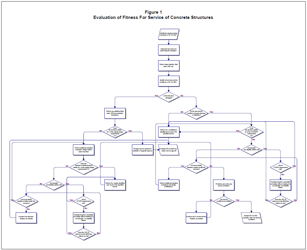
- A concrete structure may be reused without modification if changes in service conditions result in loads that do not increase member stresses or deflections, see Figure 1.
- A concrete structure may be reused without modification if changes in service result in loads for which the structure satisfies all of the requirements of the current ACI Code and EP 4-3-1, see Figure 1.
- A concrete structure may be reused without modification if changes in service conditions result in loads for which the structure satisfies all strength and stability requirements in current ACI Code and EP 4-3-1, and either meets or fails to meet in a safe manner serviceability and other requirements, as approved by the Lead Structural Engineer, see Paragraph 8.7 and Figure 1.
- In the evaluation of FFS of existing concrete members that are part of a larger structure being modified, but not undergoing alteration themselves, the existing members shall satisfy all of the requirements of the code(s) in-place at the time of their construction. In addition, the change in service can not create an unsafe condition in terms of safety of personnel, egress, fire protection/resistance, etc.; and the modification shall be designed such that it does not create a violation of existing code(s) requirements in the unaltered members, see Figure 1.
- Damaged concrete structures shall be repaired to the extent determined by the analytical evaluation and shall satisfy all of the original design's strength and stability requirements in the repaired condition, and shall either meet or fail to meet in a safe manner serviceability and other requirements, as approved by the Lead Structural Engineer, see Paragraph 8.7 and Figure 1.
- Concrete that has been exposed to fire of such temperature and duration that calculations show the concrete reached a temperature greater than 570°F shall be removed and replaced, or the strength shall be reduced accordingly by the Lead Structural Engineer.
- (*)Under the conditions specified in Paragraphs 8.3 and 8.5, if a change in service results in a failure to meet existing code(s) requirements which in the judgment of the Lead Structural Engineer relate only to the serviceability, maintenance and/or aesthetics of the structure and do not affect the long-term safety and operability of the structure or the associated unit, the change in service may be permitted as approved in writing by the Lead Structural Engineer, see Figure 1.
- If a concrete structure fails to satisfy strength and stability requirements for a change in service, modifications or further changes in service or loads shall be made to bring all members into compliance, see Figure 1.
- When evaluating the fitness for service of a concrete structure needing modifications, an economic evaluation of the cost-effectiveness of the modification versus replacement shall be performed prior to recommending reuse with modifications, see Figure 1.
REPAIR AND MODIFICATION
- General Requirements for Repair and Modification
- (*)Repair and modification procedures shall be submitted to the Owner's Engineer for approval.
- The design for repairs and modifications shall be in accordance with the current ACI standards,
e.g. ACI 318, and the requirements of local jurisdictions. In the case of conflicts, the more stringent requirements shall apply. Existing portions of structures that are not to be modified do not need to be re-designed to comply with existing codes, unless an unsafe condition would otherwise exist, see Paragraph 8.4.
- Materials of construction for reinforced concrete repairs and modifications shall comply with EP 4-3-1,EP 4-3-2, and this Practice.
- Selection of Repair and Modification Methods
- Patch repairs shall be used when surface concrete is damaged and reinforcing bar cover must be re-established. These repairs should be performed as soon as possible following identification of the problem since reinforcing bar corrosion will occur.
- The particular patch material used shall be based on the extent and depth of surface damage as given in Paragraph 9.3.
- Shotcrete shall be used for patch repair when a large area is involved and forming will be costly or impractical. Shotcrete shall not be used on repairs where depth varies by more than one-half of the average depth.
- Selection of repair methods for active and dormant cracks shall be based on Table 2 and Table
3. The progression of growing cracks shall be stopped by some form of structural or operational modification before these types of cracks are repaired. Alternatively, fracture mechanics principles may be used to show that crack growth is acceptable, see Paragraph 6.3.
- (*)Repairs and modifications that require strengthening or stiffening shall be evaluated on a case-by-case basis. These repairs shall be reviewed and approved by the Lead Structural Engineer. Acceptable repair methods include, but are not limited to:
- Bracing with reinforced concrete or steel members
- Post-tensioning and grouting
- Demolition of affected structures and replacement with concrete members that have shear and moment continuity with the remaining structure.
- Demolition of affected structures and replacement with steel members.
- When evaluating repair or modification options, the impact of construction on operations and the constructability of the design shall be considered.
- Selection of Materials
- Materials for concrete repairs shall be selected based on consideration of dimensional stability (shrinkage), coefficient of thermal expansion, modulus of elasticity, permeability, chemical compatibility, and electrical properties, as appropriate.
- (*)Concrete used in the construction of portions of structures being added to existing concrete structures shall have the same specified compressive strength as the existing concrete, unless a higher strength concrete is otherwise approved by the Owner's Engineer.
- (*)Unless otherwise specified by the Owner's Engineer, high early strength concrete shall be used in all modifications to existing structures.
- (*)Unless otherwise specified by the Owner's Engineer, concrete patch repair mortars shall be Type III, and shall be used only when the patch repair is greater than 1.5 inches thick. An expansive agent shall be used in the mix, and the addition of superplasticizers or accelerators shall be considered.
- (*)Unless otherwise specified by the Owner's Engineer, polymer concrete or mortars shall be used for 1/2 inch to 1-1/2 inch thick patch repairs. In normal patch repairs, polymer concrete and mortars shall be limited to latex-modified mortars (less than 20% by weight), or epoxy mortars (1 part resin to 3 parts concrete-sand). In thin, small patch repairs requiring special chemical resistance, polyester resin concrete or mortars may be considered.
- (*)For patch repairs less than 1/2 inch thick, materials formulated for overlaying or topping shall be used, except that epoxy mortars may be used on shallow pits, scaling and popouts.
- (*)Type III concrete shall be used for full depth patch repairs, unless otherwise specified by the Owner's Engineer. The concrete, aggregate and admixtures shall comply with EP 4-3-1. An expansive agent shall be used in the mix, and the addition of superplasticizers and accelerators shall be considered. Aggregates used shall be smaller than 1/2 the thinnest dimension of the repair or the smallest clearance.
- (*)Grouts shall be used to fill voids and large cracks. Cement-sand, polymer and fiber- reinforced grouts are acceptable, see EP 4-2-9 for grout materials, installation and curing requirements.
- (*)Fiber-reinforced grouts, mortars and concrete shall have 4 to 6% polypropylene fibers, 2 to 3% steel fibers or 2 to 4% glass fibers.
- (*)All reinforcing steel used in repairs, deformed bar or welded-wire fabric, shall be in accordance with EP 4-3-1 and EP 4-3-3.
- (*)Materials for shotcrete repairs shall comply with Paragraph 9.7.
- (*)Bonding agents shall not be used when fresh concrete is to be applied to hardened concrete, unless specified by the Owner's Engineer. Bonding agents shall be latex emulsions or epoxies (100% solids), when used. When not using bonding agents, existing surfaces shall be wetted for a period of 24 hours prior to the placement of new concrete.
- Preparation for Repairs and Modifications
- Temporary shoring shall be used as required by this Practice, see Paragraph 4.4.
- All damaged surface concrete shall be removed by one of the methods specified in Paragraph
9.4.4. Edges shall be cut square, not feathered.
- Removal of damaged concrete shall continue until such time that aggregate is being fractured, rather than loosened in whole pieces.
- Large damaged areas shall be removed by saw or water cutting, or jackhammering. Water or abrasive blast methods shall be used for removal of loose, fine materials after the initial cutting or jackhammering.
- If concrete removal exposes more than half of the perimeter of reinforcing steel, the remaining concrete around the steel shall be removed to provide a minimum clearance of 1.0 inch if the shotcreting repair method is used, or 1/4 inch plus the size of the maximum aggregate to be used in a concrete placement repair.
- All rust and loose scale shall be removed from exposed reinforcing steel.
- (*)If specified, bonding agents shall be applied as required for the specific repair materials. Otherwise, surfaces shall be wetted in accordance with Paragraph 9.3.
- Other construction preparation shall be in accordance with EP 4-3-2.
- Construction Requirements
- Except as given in Paragraphs 9.6 through 9.9, repairs and modifications shall be constructed in accordance with EP 4-3-2.
- Construction rigging and heaving lifting shall be in accordance with EP 4-9-1.
- Patching Repairs
- Patch repairs shall be performed after the damaged concrete has been removed and the surface has been prepared in accordance with Paragraph 8.4.
- Patch materials shall be used to bring the concrete member back to its original dimensions. Forms may be required. See EP 4-3-2 for formwork requirements.
- Original embedded items and/or additional reinforcing steel and embedded items shall be placed and grouted into position prior to patching.
- Concrete materials shall be placed, cured and finished in accordance with EP 4-3-2. Polymeric patching materials and overlays shall be placed, cured and finished in accordance with manufacturer's recommendations. Grouts shall be placed, cured and finished in accordance with EP 4-2-9.
- Shotcrete Repairs
- Unless otherwise specified by the Owner's Engineer, shotcrete materials shall be Type I or II concrete with well-graded aggregate having a maximum size of 0.4 inches, and a maximum water-cement ratio of 0.4. Fiber may be added in the proportions given in Paragraph 9.3.7. Epoxy bonding agents, latex-modified cement slurries or neat cement slurries may be used to improve bonding of shotcrete materials, if specified. See Paragraph 9.3.
- In addition to the preparation required in Paragraph 9.4, the perimeter of an area that will receive shotcrete shall be routed 1.0 inch deeper than the general repair area to key in the repair.
- Reinforcing bars or welded-wire fabric may be specified to provide further reinforcement. Maximum bar size shall be limited to No. 5, unless it is shown by tests that larger bars can be adequately encased. There shall be a minimum of a 2-1/2 inch clearance between parallel bars equal to or less than No.5, or a minimum of six times the bar size if larger bars are used. Splices shall be the non-contact lap-type with at least a 2-inch clearance between bars.
- Unless otherwise specified, concrete shall be removed to a minimum depth of one-inch behind exposed rebars, prior to shotcrete application.
- The shotcrete method shall not be used with spiral-tied columns.
- Unless otherwise specified by the Owner's Engineer, shotcrete shall be placed using the dry- mix method. An experienced shotcrete contractor shall be used in the application of shotcrete materials
- Shotcrete shall not be applied if the ambient temperature is expected to be less than 40°F at any time during the first seven days after application of the material.
- Shotcrete repairs shall be kept moist and above 40°F for a minimum of 7 days after application of the material. For the first 24 hours, the shotcrete shall be kept continuously moist, for the remainder of the seven days, fog spray or a moisture-retaining cover or membrane shall be maintained.
- Any damage, accumulated loose aggregate or rebound that occurs during placement shall be removed and replaced.
- Accelerators shall be atomized at the applicator nozzle.
- Crack Repairs
- (*)A detailed procedure for any proposed crack repair shall be submitted to the Owner's Engineer for review.
- Grout injection repairs, using epoxy grout, shall be limited to cracks greater than 0.002 inches wide and less than 0.25 inches wide. The procedure for epoxy grout injection shall be as follows:
- In addition to any preparation required in Paragraph 9.4, cracks shall be cleaned of oil and grease unless special grouts that displace these contaminants are used.
- Drill holes along the crack for injection nozzles. Hole spacing shall be at least the depth of the crack, and the holes shall extend 1/2 to 1-1/2 inches into the crack.
- If the crack is vertical, start injection at the lowest nozzle and proceed upward. If the crack is horizontal, start at one end and proceed to the other end. Injection pressure and flow speed shall be based on manufacturer's or contractor's recommendations for the crack size and location.
- Continue grouting until the crack is completely filled.
- When appropriate, based on the condition of the crack and the size of the structure, a termination hole shall be drilled at the end of the crack, approximately 1/2 inch in diameter and to the full depth of the structure or a minimum of 4 inches. Once crack-filling is completed, the drill hole shall be completely filled with epoxy grout.
- Gravity fed cement-sand or epoxy grouting repairs shall be limited to surface cracking on horizontal surfaces, slabs and pavements that are less than 0.004 inches deep. Gravity fed grouts shall be brushed over the surface to completely fill all cracks.
- The general procedure in Paragraph 9.8.1 shall be followed for the route-and-seal method of repairing surface cracks, except the crack shall first be routed. A groove, approximately square and 3/8 to 1/2 inches on a side, shall be cut into the surface over the length of the crack.
- The use of the plug-and-seal method for repairing cracks in open-top walls shall be limited to nearly vertical and straight cracks. A vertical hole, 2 to 3 inches in diameter, shall be drilled at the centerline of the wall, centered on the crack, from the top of the wall to the end of the crack. Grout shall be fed into the crack from this top hole.
- Overlaying or topping materials shall be brushed or rolled-on over large areas with patterned surface cracks, in accordance with manufacturer's recommendations.
- Stitching dogs used to repair structural cracks shall be sized and spaced based on the tensile forces that must be transferred across the crack. Stitching dogs shall be anchored into sound concrete on either side of the crack using epoxy grout. The ends of the crack shall be drilled to blunt the crack. Epoxy grout shall be used to completely fill all voids.
- Post-tensioning repairs shall be designed and installed by experienced post-tensioning contractors. Post-tensioning reinforcement shall cross structural cracks at approximately a 90° angle.
- Special Repair Techniques
- Pre-placed Aggregate Concrete (PAC) may be used when repairing underwater or mass concrete structures not subject to freeze-thaw problems. The procedure for PAC repairs shall be as follows:
- Remove damaged concrete and form.
- Install grout pipes, 3/4 to 1 inch NPS, split or perforated, within 3 inches of the base of the formwork and at a spacing of 4 to 12 feet in all directions, thereafter.
- Place washed, coarse aggregate, ½-inch minimum size, in the formwork. The void ratio shall be 30 to 40%.
- Grout as soon as possible after placing aggregate. The grout shall have a flow time of 12 to 24 seconds in accordance with ASTM C939. A 1:6 cement-sand grout with fly ash and sand shall be used. The sand shall have 100% passing a No. 8 sieve and at least 95% passing a No. 16 sieve.
- Seal-off grout pipes as the material level exceeds the height of the pipe's port. Continue grout application until the formwork is filled.
- Maintain pressure, typically 10 to 15 psi, on the grouted material for at least one hour after the formwork has been filled.
- Slabjacking may be used to raise pavements and slabs on grade. The following procedure shall be used for slabjacking:
- Holes, 1-1/2 to 2-1/2 inches in diameter, shall be drilled through the slab or pavement, staggered at 5 to 8 foot spacing in all directions. Holes shall be a 1-1/2 to 2-1/2 feet from all edges.
- Cement-sand grouts to be used shall have 5 to 10% Portland cement and 5 to 15 gallons of water per 94 pounds of cement. Sands used shall have 100% passing a No. 8 sieve.
- Cement-sand grout on the thicker end of the range given in Paragraph 9.9.2.b shall be used to raise the slab or pavement to the proper elevation using one-half of the holes. This process shall start at the lowest point, using one hole at a time, but frequently moving to other holes. Typically, 25 psi will be required to lift a slab or pavement.
- Once the desired elevation is obtained, a cement-sand grout on the thinner end of the range given in Paragraph 8.8.2.b shall be pumped through the remaining holes to fill all voids. This process shall start at one end, in a corner, and shall progress to the other end of the slab or pavement.
10.0 POST-REPAIR OR MODIFICATION TESTING AND INSPECTION
- (*)When specified by the Owner's Engineer or required by local building officials, core specimen(s) shall be taken from a repair area. The sampling method and evaluation of the specimen(s) shall comply with Paragraph 5.4. If a crack is included in the repair area, a core specimen shall be centered on the crack.
- Strength tests of shotcrete specimens shall be made and evaluated in accordance with the UBC. In addition, visual examination and special inspection of shotcreting shall be in the accordance with the UBC.
- Inspection and testing of concrete construction and materials shall be in accordance with EP 4- 3-1, EP 4-3-2 and EP 4-3-3.
- (*)Additional inspection and testing of repairs and modifications to concrete structures shall be as required by local building officials, or the Owner's Engineer.
- The Concrete Construction Inspection Checklist, EP 4-3-2C, shall be used to document field testing and inspection of structures modified or repaired in accordance with this Practice.
11.0 TABLES
TABLE 1
MINIMUM DEPTH OF CORE SPECIMEN DRILLING
(SEE PARAGRAPH 5.4 FOR OTHER REQUIREMENTS)
| TYPES OF CONSTRUCTION | THICKNESS OF COMPONENT (IN.) | MINIMUM DEPTH OF DRILLING (IN.) |
|---|---|---|
| Slabs, pavements, walls, foundations, and other components accessible from only one side | 12 or less Greater than 12 |
1. Entire depth 2. 12 |
| Suspended slabs, walls, foundations and other components accessible from two or more sides | 1. 6 or less 2. 6 to 24 | Entire depth Greater of 6 or 1/2 thickness |
| Massive components | Greater than 24 | 24 |
TABLE 2
REPAIR OF ACTIVE CRACKS (1)
| CRACK CHARACTERISTICS | REPAIR METHODS |
|---|---|
| I. Patterned Cracks | 1. Overlay |
| II. Isolated Cracks | |
| 1. Strength Required | Redesign and add expansion joint Stitch Post-tension and grout |
| 2. Strength not Required | Grout |
NOTES:
(1) The drill-and-plug technique may be used to repair cracks in open-top walls, see Paragraph 9.8.5.
TABLE 3
REPAIR OF DORMANT CRACKS(1)
| CRACK CHARACTERISTICS | REPAIR METHODS(1) |
|---|---|
| I. Patterned Cracks | |
| 1. No water problem or minor water problem | Overlay Route and seal |
| 2. Severe water problem | 1. Overlay |
| II. Isolated Cracks | |
| 1. Strength Required | Redesign and add expansion joint Stitch Post-tension and grout |
| a. No water problem or minor water problem | Inject epoxy grout Stitch Post-tension and grout |
| b. Severe water problem | Post-tension and grout |
| 2. Strength not Required | Grout |
NOTES:
(1) See Note 1 in Table 2
12.0 FIGURES
FIGURE 1
EVALUATION OF FITNESS FOR SERVICE OF CONCRETE STRUCTURES
© 2026 Inflection Point Engineering, LLC. All rights reserved. The content of this page — including calculation methods, reference data, written analysis, interactive tools, and source code — is the intellectual property of Inflection Point Engineering, LLC and is protected under applicable copyright, trademark, and trade secret laws. Unauthorized reproduction, redistribution, modification, or derivative use in whole or in part is prohibited without prior written consent.
Disclaimer. This material is provided for informational and educational purposes only and does not constitute professional engineering advice. Calculations, reference data, and methodologies are based on published standards and accepted engineering practice but are not a substitute for engineering judgment, site-specific analysis, or review by a licensed Professional Engineer. Inflection Point Engineering, LLC makes no warranties, express or implied, regarding the accuracy, completeness, or fitness for a particular purpose of any content presented here, and shall not be liable for any direct, indirect, incidental, or consequential damages arising from its use. Users assume all risk associated with applying this content to real-world design, operations, or decisions.
© 2026 Inflection Point Engineering, LLC. All rights reserved.