 Section 4 — Structures and Foundations
Grouting Baseplates for Structural Steel and Equipment
IPE Engineering Practice IPE-EP-4-2-9
Document number: IPE-EP-4-2-9 · Section: 4 — Structures and Foundations
SCOPE
- This Practice covers requirements for grouting base and slide plates, and attaching structural steel and equipment to concrete foundations. For installation of rotating equipment, requirements can be found in EP 6–8–1.
- Any deviation from this Practice must be approved by the procedures described in EP 1–1–3.
- An asterisk (*) indicates that a decision or approval by the Owner or the Owner’s Engineer is required, or that additional information is furnished by the purchaser.
- A revision bar indicates all changes made to this Revision.
- Documentation required for grouting performed in accordance with this Practice is given in Table 4.
2.0 REFERENCES
The latest edition of the following standards and publications are referred to herein.
STANDARDS AND PUBLICATIONS
| IPE Engineering Practices |
|---|
| EP 1–1–3 Deviations to IPE Engineering Practices EP 4–2–9C Grouting and Baseplates for Structural Steel and Equipment Inspection Checklist EP 6–8–1 Field Storage and Installation of Rotating Equipment EP 10–3–8 Galvanized Coatings |
| ACI Standards and Special Publications |
| 305R Hot Weather Concreting 306R Cold Weather Concreting 351 Grouting of Equipment and Machinery |
| AASHTO Standard |
| T26 Standard Method of Test for Quality of Water to be Used in Concrete |
| API |
| 610 Centrifugal Pumps for General Refinery Service |
| ASTM |
| A36 Standard Specification for Structural Steel C33 Standard Specification for Concrete Aggregates C109 Standard Test Method for Compressive Strength of Hydraulic Cement Mortars (using 2–in or 50–mm cube specimens) |
STANDARDS AND PUBLICATIONS (CONT.)
| ASTM (Cont.) |
|---|
| C150 Standard Specification for Portland Cement C191 Standard Test Method for Time of Setting of Hydraulic Cement by Vicat Needle C531 Standard Test Method for Shrinkage and Coefficient of Thermal Expansion of Chemical–Resistant Mortars, Tile Grouts, and Monolithic Surfacings C579 Standard Test Method for Compressive Strength of Chemical–Resistant Mortar and Monolithic Surfacings C827 Standard Test Method for Change in Height at Early Ages of Cylindrical Specimens from Cementitious Mixtures C1107 Standard Specification for Packaged Dry, Hydraulic - Cement Grout (Nonshrink) |
| Corps of Engineers Specification |
| CRD 621-91 Specification for Packaged Dry, Hydraulic–Cement Grout (Nonshrink) |
DEFINITIONS
- Contractor - Company or business that agrees to furnish materials or perform specified services at a specified price and/or rate to the Owner.
- Heavy Machinery - Rotating equipment having reciprocating or rotary masses as the major moving parts (such as reciprocating or rotary compressors, pumps, engines, and turbines), and having a gross plan area of more than 20 square feet or a total weight greater than 4,000 pounds.
- Inspector - A Inflection Point Engineering, LLC appointed engineer or inspector.
- Light Machinery - All rotating equipment that is not classified as Heavy Machinery.
- Owner - Inflection Point Engineering, LLC.
- Owner’s Engineer - A Inflection Point Engineering, LLC appointed engineer.
- Purchaser - The party placing a direct purchase order. The purchaser is the Owner’s designated representative.
GROUT, BASE AND SLIDE PLATE MATERIALS
- Grout
- Grout materials shall be in accordance with Table 1.
- Storage of grout materials shall be in accordance with the manufacturer’s recommendations and the following:
- Grout components shall be delivered to the construction site in moisture–proof bags. Bags shall be stored in a dry, weather–proof area within the temperature range of 40oF to 90oF.
- Material that becomes damp or defective shall be removed from the site.
- Storage time of non–shrink cement grout mix shall be limited to six months.
- Storage time of epoxy grout shall be per manufacturer’s recommendation.
- Base and Slide Plates
- (*)Steel conforming to ASTM A 36 shall be used for base and slide plates. Galvanized, base and slide plates shall be specified by the Owner’s Engineer.
- (*)Unless otherwise specified by the Owner’s Engineer, slide plates shall have Teflon pads shop bonded to 10–gage AISI Type 304 stainless steel plate. The bond between the Teflon and stainless steel shall be fully effective for –320oF to 400oF temperature range. The Teflon pads shall be made of 100% virgin Teflon (TFE) with graphite or ground glass fibers and reinforcing aggregates. The sliding coefficient of static friction shall not be greater than 0.10.
- (*)For temperatures between 400oF and 800oF, insulated Fluorotemp® slide bearings or an Owner’s Engineer–approved equivalent shall be used.
5.0 GROUT SELECTION CRITERIA AND MINIMUM THICKNESS
Grout selection and minimum thickness shall be based on the information in Table 2.
INSTALLATION AND TESTING OF GROUT
- Contractor Specification
- (*)The Contractor’s grouting specification shall include as a minimum the following list of information. NOTE: Foundation designs shall be submitted to the machinery vendor for review per applicable API Standards or as otherwise specified by the Owner’s Engineer. Specific requirements for setting, leveling, and grouting shall be included in the Contractor’s grouting specification:
- Grouting mortar type for individual machinery applications.
- Specific requirements of the machinery vendor and grouting manufacturer.
- Procedures for removal or retention of shims, tightening of anchor bolts, and for packing or grouting of anchor bolt sleeves.
- Provisions to be made for weather protection or artificial temperature conditioning (i.e., hot and cold weather practices, as applicable). Information from sources such as ACI 305, ACI 306, and ACI 351 shall be used.
- Mixing and application procedures for field–mixed cement–sand grouting mortar, where applicable.
- Safe handling practices for epoxy grout systems.
- (*)The grouting specification shall be submitted to the Owner’s Engineer for approval. Machinery shall be grouted in compliance with Appendix L of APl 610 or other applicable APl Standards, Section 6.0 of EP 6–8–1, and this Practice.
- Surface Preparation
- Bonding surfaces of the machine base or support shall be per the following:
- Cement–sand grout: Metal surfaces shall be free of loose mill scale; oil or grease; and any debris that may interfere with complete bearing.
- Epoxy grout: Metal surfaces shall be cleaned and pre-coated with epoxy resin per the requirements of applicable APl Standards for rotating machinery and EP 6–8–1, or as otherwise recommended by the grout manufacturer.
- Nonbonding surfaces, such as leveling screws, wedges, and shims that are to be removed shall be coated per the grout manufacturer’s recommendations, to prevent adherence of the grout.
- (*)Modifications or repairs to existing concrete foundations shall have cured a minimum of 24 hours for regular concrete, and 12 hours for high–early–strength concrete before grouting. The Owner’s Engineer shall approve provisions for such repairs, modifications, and new construction.
- Bonding surfaces of concrete foundations shall be per the following:
- Laitance (layer of weak, non-durable concrete material) shall be removed by chipping to a depth of at least 0.50 inches from the surface of new foundations, but not less than that required to reach sound aggregate. All oil–soaked concrete on re–used foundations shall be removed by chipping then cleaned with muriatic acid.
- Surfaces shall be clean and free of loose particles, oil or grease; surfaces may require sandblasting and/or solvent wash.
- Where cement–sand grout is to be used, all free water shall be removed from the surface and from bolt holes just prior to grouting.
- Where epoxy grout is to be used, surfaces shall be clean and dry immediately prior to grouting.
- Forms
- Forms for grout Types II and Ill shall be built of materials with adequate strength to withstand the placement of grout.
- Forms for non–shrink cement grout, Type II, shall be tight against all surfaces and joints shall be sealed with tape. Form oil shall be used for easy form release.
- Forms for epoxy grout, Type Ill, shall be watertight with chamfer strips in place. Caulking shall be used on all joints. Forms shall be lined with polyethylene or three coats of paste wax for easy form release.
- One side of the forms shall be four (4) to six (6) inches higher than the base plate on that side when using hydraulic head pressure for placing.
- Air relief holes a minimum of 1/4 inch in diameter must be provided at every recessed base plate corner.
- Mixing
- Grout shall be mixed in accordance with the manufacturer’s recommendations.
- Non–shrink cement grout shall be added to water to obtain the desired consistency.
- Epoxy grout components shall be conditioned to a temperature between 70°F and 85°F before use. Epoxy hardener shall first be added to resin and thoroughly mixed for 2 to 3 minutes without whipping air into the mix. Low speed mixer or hand stirring shall be used. Mixed resin and hardener shall then be placed into clean mortar mixer and the entire bag of aggregate added. Epoxy grout component ratios shall not be altered and no solvents or thinners added to the mix. Epoxy grout has limited shelf life, and shall not be used after the amount of time past mixing recommended by the manufacturer.
- Non–shrink cement grout shall be mixed in accordance with the manufacturer’s instructions on the container, usually between 3 and 5 minutes, for uniform consistency.
- Epoxy grout shall be mixed until aggregate is uniformly wetted.
- A mortar mixer shall be used instead of a concrete mixer for mechanical mixing of grout.
- Re-mixing of grout by adding more water or re-mixing of stiffened grout is not permitted.
- Setting, Leveling and Grout Installation
- Wedges, shims, or leveling screws shall be used to position the machine or structure at its proper height, and to level the machine. Wedges shall not be retained.
- (*)Unless otherwise approved by the rotating equipment engineer, all shims used in grouting machinery shall be removed after grouting. Where shims are to be retained after grouting other equipment or structures, the shims have full contact with the foundation.
- Grout shall be continuously placed from one side of the baseplate, and only in one direction.
- The required grout, selected in accordance with this Practice, shall be placed to completely fill all spaces under the baseplate. Anchor bolt sleeves shall be completely filled, except for machinery which shall have sleeves protected to prevent filling in accordance with
EP 6–8–1.
- The grouting pressure hydraulic head shall be maintained by keeping the level of grout in the head box above the bottom of the base plate. The head box shall be filled to the maximum level and grout worked down to the top of the base plate.
- Shims used for temporary leveling of equipment and base plates shall have no sharp corners, and shall be removed after the grout has obtained sufficient strength to carry the baseplate loading. Voids left by the removal of shims shall be filled with a second placement of grout. All shims that are to be retained shall be covered with grout.
- Finishing and Curing
- After cement grout has reached final set, it shall be trimmed back to the level indicated on design drawings.
- The top surfaces of epoxy grout may be finished by trowelling with a steel trowel moistened with oil before set.
- After sufficient set has been attained, the excess grout shall be trimmed away. The finished surface shall slope away from the base (approximately 1:24).
- Curing of grout shall be in accordance with the manufacturer’s recommendations and Table 1.
- The temperature of the baseplate and foundation shall be maintained within 5°F of each other between 40° and 90°F.
- Checking for Voids
- After the grouting mortar has cured, base plates for rotating or oscillating machinery shall be hammer tested for voids. Where voids are indicated, the base plate shall be drilled and tapped to add a grease fitting at one edge of the void and a vent hole shall be drilled at the opposite edge of the void. The tapping operation shall be done dry; without the use of cutting oil. The void shall be filled by injecting epoxy grout with a grease gun.
- Where cement–sand grout mortar is used, the grout manufacturer’s recommendation shall be followed regarding required curing time before filling voids with epoxy grout.
- Surface Protection
- Cement–sand grouting: After the grout has completely dried, all exposed grouting material shall be coated with 2 coats of an oil–and–alkali–resistant coating, such as Phenolic Aluminum (2- compartment) paint. The grout surface shall be neutralized prior to painting.
- Painting of exposed epoxy grouting material is not required.
- Testing
- The contractor shall be responsible for preparing, storing, curing and transporting the test samples to the laboratory for testing.
- Grout shall develop its required compressive strength in accordance with ASTM C109 modified for cement grouts and ASTM C579 for epoxy grout.
- Nine test cubes shall be made for each grout delivery. Tests shall be made of three (3) cubes at the following intervals: cement grout 24 hours, 7 days and 28 days. Epoxy grout 24 hours, 2 days and 7 days.
- (*)All test results shall be submitted to the Inspector for review and approval. Results shall be recorded on EP 4–2–9C or in an alternative format approved by the Inspector.
BASE PLATE DESIGN AND INSTALLATION
- (*)Unless otherwise specified by the Owner, all horizontal drums and heat exchangers shall be provided with base plates. Base plates shall be greased prior to equipment installation if slide plates are not provided.
- Equipment, including horizontal drums, heat exchangers, and piping systems shall be checked for horizontal movement at support points due to thermal expansion or contraction under the most severe conditions. If this movement results in an overstress of the equipment or a large overturning movement on the foundation, base and slide plates shall be provided to reduce friction forces. A typical slide plate detail for a horizontal drum or heat exchanger is shown in Figure 1A.
- Installation of base and slide plates shall be in accordance with the following:
- Grouting of base plates, see Figure 1B, shall be in accordance with the requirements of this Practice. Base and level plates shall be installed at the elevation shown on the applicable foundation drawings.
- Anchor bolts for horizontal vessels and exchangers shall be tightened down on the fixed support, and nuts shall be only finger tightened and then backed off 1/3 turn and threads checked with a chisel and hammer on sliding support, or a jamb nut shall be provided.
- Where appropriate, baseplate details shall comply with APl Standards for machinery. Figure 2A and Figure 2B show typical machinery baseplate details.
8.0 TABLES
TABLE 1 REQUIREMENTS FOR GROUT MATERIALS
| Type | Description | Curing Requirements |
|---|---|---|
| I | Dry–Pack grout shall consist of one part cement to two parts sand with sufficient water to provide a mix stiff enough to be placed by tamping. | Dry–Pack Grout: 1. Grout shall be covered with rags or burlap and moist cured for a minimum of 3 days. |
| ASTM C150, Type III cement shall be used. Fine aggregate shall comply with ASTM C33. Water shall be clean and free from injurious amounts of oils, acids, alkalies, organics, and other deleterious materials, per AASHTO T26. |
Forms shall remain in place for 24 hours. Temperature of base plates and supporting concrete shall be maintained between 40°F and 90°F during grouting and for a minimum of 24 hours after placing. |
|
| II | *Non–Shrink Cementitious Grout shall be a Non metallic fluid pre–mixed factory packed Five Star, Master Builders, Sauereisen or approved equal, meeting ASTM C1107 Grade C, at a temperature between 40° and 90° F, and the following requirements: | Non–Shrink Cementitious Grout: 1. Grout shall be cured in accordance with manufacturer’s specifications and recommendations. |
| 1. Exhibit no visible bleeding two hours after placement. | 2. Forms shall remain in place for 24 hours. | |
| Grout shall show no shrinkage and a maximum of 4.0 percent expansion at any time before initial set and tested according to ASTM C827. Grout shall show no shrinkage and a maximum of 0.1 percent expansion in the hardened state when tested according to CRD 621. |
3. Temperature of base plates and supporting concrete shall be maintained between 40°F and 90°F during grouting and for a minimum of 24 hours after placing. | |
| 4. Compressive strength minimum of 5,000 psi at 28 days and minimum strengths as listed, in accordance with ASTM C109 modified in the following Table: |
TABLE 1 (CONTINUED) REQUIREMENTS FOR GROUT MATERIALS
| Type | Description | Curing Requirements |
|---|---|---|
| II | COMPRESSIVE STRENGTH (PSI) (ASTM C109) Grout shall show initial set time of not less than 60 minutes when tested according to ASTM C191. Grout shall contain no metallic substances, water reducing agents, accelerators, super plasticizers or other materials that contribute to drying shrinkage. Technical service shall be provided by the manufacturer of grout upon request of Contractor. Water shall be as per AASHTO T26. |
|
| III | *Epoxy grout shall be Ceilcote, Escoweld, Five Star, Sauereisen, or approved equal, meeting the following requirements: Grout shall be flowable and a 100 percent solids system. Grout shall show no shrinkage and a maximum of 4 percent expansion when tested in accordance with ASTM C827 modified for use with epoxy grout. |
Epoxy Grout: Grout shall be cured in accordance with manufacturer’s specifications and recommendations. Forms shall remain in place for a minimum of 24 hours after placing grout. |
TABLE 1 (CONTINUED) REQUIREMENTS FOR GROUT MATERIALS
| Type | Description | Curing Requirements |
|---|---|---|
| III | Compressive strength shall be determined by ASTM C579 attaining the minimum strengths listed below: GROUT COMPRESSIVE STRENGTH (PSI) (ASTM C579) Peak exotherm temperature of a 2-inch diameter by 4-inch high cylinder of grout shall not exceed 95°F when tested at 75°F material and air temperatures. Grout shall not exceed a coefficient of thermal expansion of 30 X 10-6 in/in/°F when tested in accordance with ASTM C531. Grout shall be capable of maintaining a flowable consistency for a minimum of 30 minutes at 70° F. |
3. Temperature of base plates and supporting concrete shall be maintained between 40°F and 80°F during grouting and for a minimum of 24 hours after placing. |
TABLE 2
GROUT SELECTION CRITERIA AND MINIMUM THICKNESS
| Equipment Description | Grout Type (1) | Minimum Thickness (inches) |
|---|---|---|
| Structural items and equipment excluding machinery | I | 3/4 |
| Light Machinery(*) | II | 1 |
| Base plates, soleplates and rails for all machinery(*) | III | 1–1/2(2) |
NOTE:
- See Table1 for grout type description.
- For machinery mounted on baseplates consisting of an arrangement of wide–flange beams or other structural members, the required grout shall be used to fill the entire volume of the baseplate created by the arrangement of structural members, see Paragraph 6.5.4 and Figure 2C.
(*) Light machinery shall be grouted with Type II grout unless otherwise specified by the IPE Rotating Equipment Engineer.
TABLE 3
SLEEVE DIMENSIONS FOR MACHINERY ANCHOR BOLTS
| Anchor Bolt Diameter | Nominal Pipe Size of Sleeve(S) | Length (in.) of Sleeve(D) |
|---|---|---|
| 5/8 | 2 | 6 |
| 3/4 | 2 | 6 |
| 7/8 | 2 | 6 |
| 1 | 2 | 8 |
| 1-1/8 | 2 | 8 |
| 1-1/4 | 3 | 10 |
| 1-3/8 | 3 | 12 |
| 1-1/2 | 3 | 14 |
| 1-3/4 | 4 | 16 |
| 2 | 4 | 18 |
| 2-1/4 | 4 | 20 |
| 2-1/2 | 4 | 22 |
TABLE 4 DOCUMENTATION REQUIREMENTS FOR GROUTING AND BASEPLATE PER EP 4–2–9
| Item | Description | Format | As–Built |
|---|---|---|---|
| 1 | Manufacturer’s grout specification | Text | N/A |
| 2 | Results of grout testing | Text | N/A |
9.0 FIGURES
FIGURE 1A
SLIDE PLATE DETAILS FOR HORIZONTAL DRUMS AND HEAT EXCHANGERS PLAN VIEW
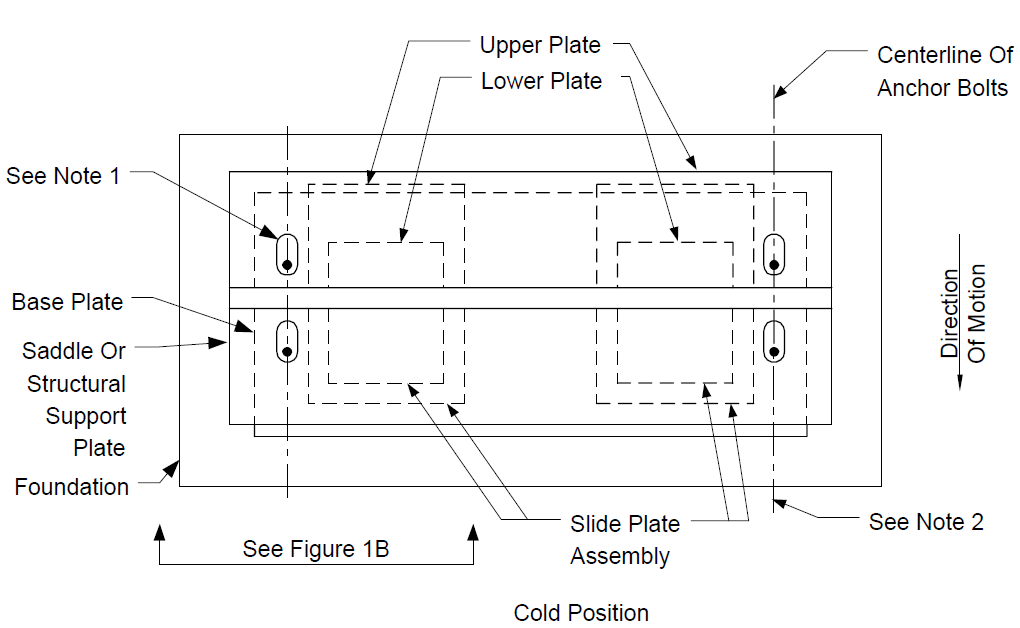
NOTES:
- Relative position of slotted holes with respect to anchor bolts (installed position) shall be shown on design drawings.
- The slot width in the saddle or structural support plate to be equal to the anchor bolt diameter plus 5/16 inch. Slot length to be equal to anchor bolt diameter plus motion due to thermal expansion or contraction plus a minimum of 5/16 inch.
FIGURE 1B
SLIDE PLATE DETAILS – ELEVATION
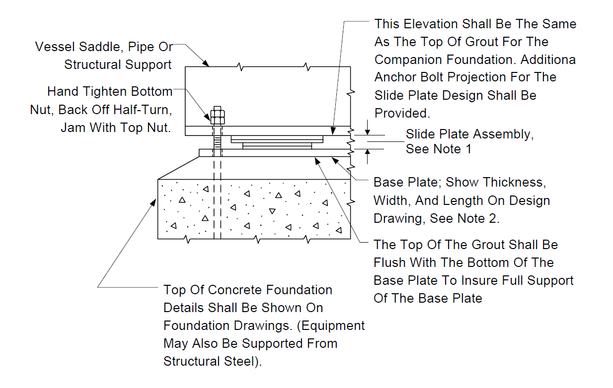
NOTES:
- AISI Type 304 stainless steel backup plates shall be specified The upper slide plate shall cover the lower slide plate a minimum of 1/2 inch for all conditions of motion.
- Base plate shall be 1/2 inch minimum thickness and galvanized per EP 10–3–8.
FIGURE 2A
TYPICAL MACHINERY BASEPLATE GROUTING DETAIL
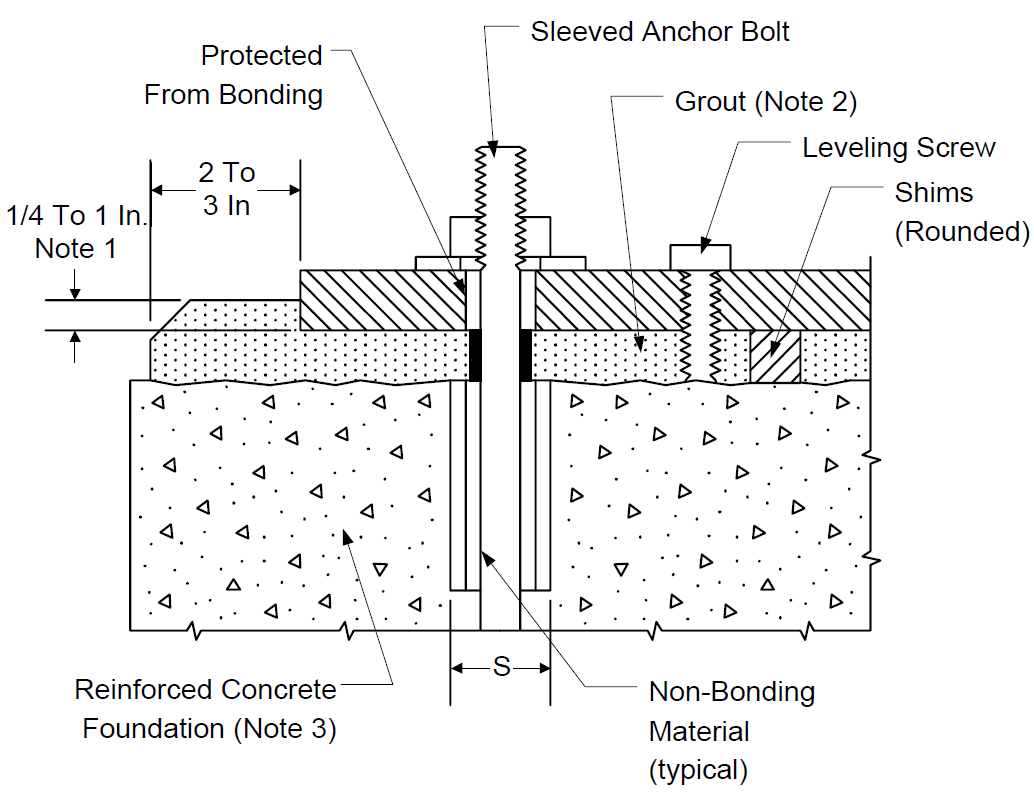
NOTES:
- Dimensions based on grout manufacturer’s recommendation (1/4-in. minimum).
- Grout thickness and type per Paragraph 5.0.
- Surface of concrete chipped and cleaned per Paragraph 6.2.
- See Table 3 for sleeve dimensions.
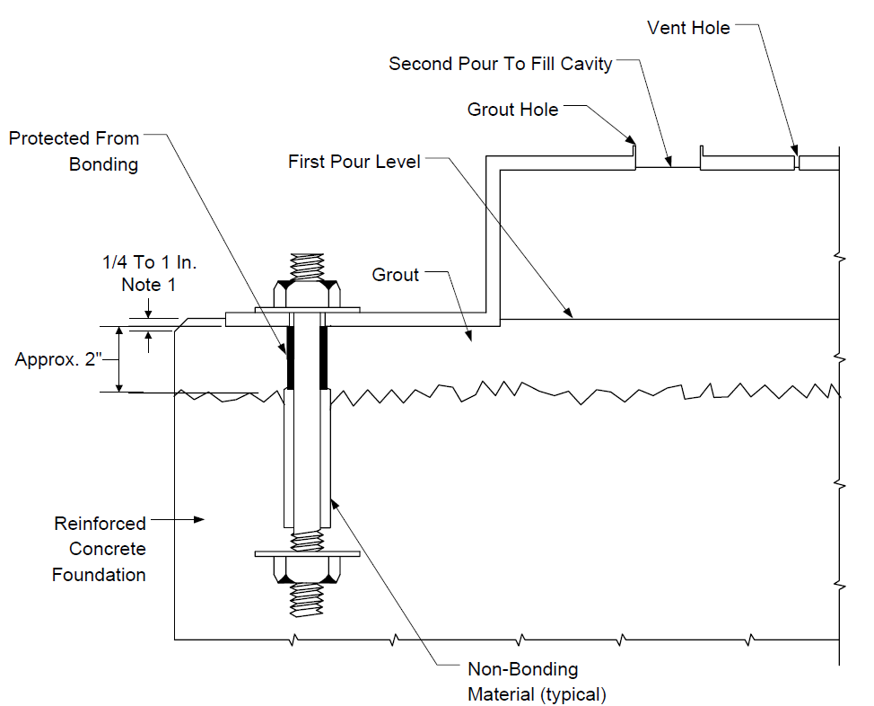
FIGURE 2B
TYPICAL MACHINERY BASEPLATE GROUTING DETAIL
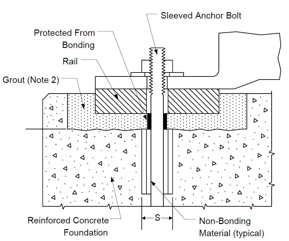
NOTES:
- Dimension based on grout manufacturer’s recommendation (1/4 in. min., 1 in. max.)
- Surface of concrete chipped and cleaned
- Grout thickness and type per Paragraph 5.0.
- See Table 3 for sleeve dimensions.
FIGURE 2C
TYPICAL HEAVY MACHINERY BASEPLATE GROUTING DETAIL
NOTES:
- Surface of concrete chipped and cleaned.
- Grout thickness and type per Paragraph 5.0.
- See Table 3 for sleeve dimensions.
© 2026 Inflection Point Engineering, LLC. All rights reserved. The content of this page — including calculation methods, reference data, written analysis, interactive tools, and source code — is the intellectual property of Inflection Point Engineering, LLC and is protected under applicable copyright, trademark, and trade secret laws. Unauthorized reproduction, redistribution, modification, or derivative use in whole or in part is prohibited without prior written consent.
Disclaimer. This material is provided for informational and educational purposes only and does not constitute professional engineering advice. Calculations, reference data, and methodologies are based on published standards and accepted engineering practice but are not a substitute for engineering judgment, site-specific analysis, or review by a licensed Professional Engineer. Inflection Point Engineering, LLC makes no warranties, express or implied, regarding the accuracy, completeness, or fitness for a particular purpose of any content presented here, and shall not be liable for any direct, indirect, incidental, or consequential damages arising from its use. Users assume all risk associated with applying this content to real-world design, operations, or decisions.
© 2026 Inflection Point Engineering, LLC. All rights reserved.