 Section 4 — Structures and Foundations
Foundations for Atmospheric Storage Tanks
IPE Engineering Practice IPE-EP-4-2-7
Document number: IPE-EP-4-2-7 · Section: 4 — Structures and Foundations
SCOPE
- This Practice covers general requirements for the design and construction of foundation pads for atmospheric storage tanks.
- This Practice does not apply to tanks used for storage of acids or other corrosive chemicals, or to refrigerated tanks.
- Any deviation to this Practice must be approved by the procedure described in EP 1–1–3.
- An asterisk (*) indicates that a decision or approval by the Owner or the Owner’s Engineer is required, or that additional information is furnished by the Purchaser.
- A Revision Bar indicates all changes made to this Practice.
- Documentation required for atmospheric storage tank foundations in accordance with this Practice is given in Table 3.
2.0 REFERENCES
The latest edition of the following standards and publications are referred to herein.
STANDARDS AND PUBLICATIONS
| IPE Engineering Practices |
|---|
| EP 1–1–3 Deviations to IPE Engineering Practices EP 4–2–1 Foundation Types and Selection Criteria EP 4–2–7C Foundations for Atmospheric Storage Tanks Inspection Checklist EP 4–3–1 Concrete Design EP 4–3–2 Concrete Construction Requirements EP 9–1–1 Atmospheric Storage Tanks EP 10–3–6 Cathodic Protection for Tank Bottoms |
| ASTM Standards |
| D471 Standard Test Method for Rubber Property-Effect of Liquids D693 Crushed Stone, Crushed Slag, and Crushed Gravel for Bituminous Macadam Base and Surface Courses of Pavements D751 Standard Test Method for Coated Fabrics D1204 Standard Test Method for Linear Dimensional Changes of Nonrigid Thermoplastic Sheeting or Film at Elevated Temperature D1556 Density of Soil in Place by the Sand-Cone Method D1557 Moisture-Density Relations of Soils and Soil-Aggregate Mixtures Using 10-lb. (4.54kg) Hammer and 18 in. (457 mm) Drop D2136 Standard Test Method for Coated Fabrics-Low-Temperature Bend Test |
STANDARDS AND PUBLICATIONS (CONT.)
DEFINITIONS
- Contractor - Company or business that agrees to furnish materials or perform specified services at a specified price and/or rate to the Owner.
- Earth Pad - The soil used to elevate tank above surface grade.
- Geotechnical Engineer - A Inflection Point Engineering, LLC engineer or designated representative appointed to carry out soil testing and field inspection.
- Inspector - A Inflection Point Engineering, LLC appointed engineer or inspector.
- Owner - Inflection Point Engineering, LLC.
- Owner’s Engineer - A Inflection Point Engineering, LLC appointed engineer.
- Pile - Structural member of timber, concrete, and/or steel, used to transmit surface loads to lower levels in the soil mass.
- Ringwall - Foundation provided under the shell to minimize shell settlement caused by the shell cutting into the soil.
SUBSURFACE INVESTIGATION
- (*)An accurate determination of the geotechnical conditions at the tank sites including, but not limited to a program of soils borings, laboratory testing and engineering analysis shall be carried out for all new tank foundations, by a Geotechnical Engineer approved by the Owner.
- The number of borings and the scope of testing and analysis will vary with the number and size of tanks, the soil characteristics and the amount of historical settlement data from tanks within the Plant. For guidelines on soils borings and sampling refer to EP 4–2–1.
- The results of a geotechnical investigation shall include an evaluation of foundation stability (general bearing capacity, local shear and potential for plastic or lateral flow) and estimates of foundation settlement at 10 and 25 years. These results shall be documented in a report that shall be part of the tank’s permanent records.
SITE IMPROVEMENT
- (*)If the results of the soils investigation indicate that calculated safety factors against foundation failures are less than 1.5 or if estimated future tank shell settlements are likely to exceed 12 inches the following site improvements shall be performed, unless otherwise approved by the Owner:
- Removal of soil that contributes most to the tank instability and settlement, and replacing it with well compacted fill. This is usually viable if total excavation depth require to remove weak soils does not exceed 10 to 15 feet. Consideration shall be given to the effect such excavation and fill will have on the water table.
- (*)Preloading the soils under the tank site (surcharge) by placing an earth mound on the site and waiting until sufficient consolidation has taken place to permit tank erection, Normally, a preload equal to 1–1/2 to 2 times the full service load of the tank is adequate to achieve the necessary consolidation. Sand drains are sometimes installed to increase consolidation rates and thereby reduce preload in–place time. Preloading can also be achieved by filling the tank with water in increments and allowing the soil to consolidate under each increment until the full load is applied. Relevelling of the tank shall be done after water preloading. The Owner shall approve the method of preloading.
- Densification of loose granular soils responsible for the instability or settlement problems by vibro-compaction techniques.
TANK FOUNDATIONS
- Earth Pads and Gravel Ringwalls
- (*)Steel storage tanks shall be supported on raised compacted earth pads with gravel ringwalls under their shells, unless conditions specified in Paragraph 6.2 or 6.3 exist. For details of gravel ringwalls, see Figure 1 through Figure 4. Earth pad foundations without gravel ringwalls shall not be used without the approval of the Owner’s Engineer.
- The predicted settlements from the geotechnical investigation shall be used in establishing final foundation pad elevations.
- (*)Any crushed stone or crushed gravel with a maximum size of 1–1/2 inches and which meets the requirements of ASTM D693 and Figure 21 shall be used to construct the gravel ringwall. Proposal to use other materials shall be approved by the Owner. Ringwall material shall be compacted to 70% relative density in accordance with ASTM D4253 and D4254. Limestone shall not be used without the approval of the Owner’s Engineer.
- The general fill used to construct the pad shall be non-corrosive, cohesive or cohesionless soil. The cohesive soil shall be compacted to a dry density equivalent to 90% of the maximum dry density obtained in ASTM D1557. The cohesionless soil shall be compacted to 70% relative density in accordance with ASTM D4253 and ASTM D4254.
- In–place density shall be determined by one or more of the methods given by ASTM D1556, ASTM D2167, ASTM D2922 and ASTM D2937.
- The area surrounding a tank shall be graded to provide adequate drainage.
- Pile Foundation
- (*)A pile or other deep foundation shall be used only with the approval of the Owner’s Engineer when:
- Deep soil deposits that are too weak to support the loads imposed by the tank underlie the tank site.
- Expected settlements are too large and cannot be reduced to tolerable limits by methods given in Paragraph 5.1.
- Construction of a viable lead containment and detection system using any other foundation system is precluded due to soil conditions.
- Pile foundations shall comply with EP 4–2–4.
- Concrete Ringwalls
- (*)Unless otherwise approved by the Owner’s Engineer, a concrete ringwall shall be used only in firm soils where settlement at the tank center is expected to be less than 6 inches, and edge cutting settlement is a concern. For details of concrete ringwalls see Figure 5 through 8.
- Concrete ringwall design and construction shall comply with EP 4–3–1 and EP 4–3–2.
- Foundation Details
- Figures listed in Table 1 shall be used in the design of tank foundations.
- As–built plan, elevation and section drawings required in the construction of the tank’s foundation shall be included in the tank’s permanent records.
LEAK DETECTION, CATHODIC PROTECTION, AND RELEASE PREVENTION BARRIER SYSTEMS
- (*)Unless otherwise specified by the Owner, new tanks shall have a leak detection and release prevention barrier system which as a minimum shall consist of:
- An impermeable membrane installed immediately below a layer of fine gravel or sand placed under the tank. The membrane shall be a coated fabric with a minimum thickness of 40 mils (1 mm). The membrane shall be protected against puncturing as recommended by the manufacturer, and shall be compatible for the type of product stored in the given tank.
- A leak detection system consisting of plastic pipes placed on top of the membrane. The number of pipes for cone–up tanks shall be obtained by dividing the tank diameter, in feet, by 10. For cone–down tanks, a minimum of one leak detection pipe, from the center sump, shall be required.
- Details for leak detection system shall be per Figure 3, Figure 4, Figure 7, Figure 8, Figure 11, Figure 12, and Figure 15 through 21.
- The leak containment and detection system specified above shall be designed to take into account expected settlements that may affect the integrity of the impermeable membrane. Slip joints, such as folds, are required to avoid rupturing the membrane.
- Cathodic protection systems shall be designed in accordance with EP 10–3–6.
- As–built plan, elevation and details of leak detection, cathodic protection and release prevention barriers shall be included in the tank’s permanent records.
- (*)Field test and inspection records for impermeable membranes shall be recorded on EP 4–2– 7C or an alternative acceptable to the Owner’s Engineer.
- Where appropriate, manufacturer’s installation, calibration and maintenance recommendations shall be documented in the tank’s permanent records.
TANK SETTLEMENT
When dealing with tank settlement, it is important to distinguish between shell and bottom settlement. The following types of settlement shall be considered in the design of atmospheric storage tank foundations:
- Shell Settlement
Shell settlement is categorized into four groups.
- Uniform shell settlement - The shell can settle uniformly so that the structure remains level. Uniform settlement of this type does not introduce high stresses in the tank shell and the tank should not need correction. It is usually easier and safer to adjust external supports for piping and other attached equipment to accommodate the tank shell settlement.
- Uniform tilt - The shell can settle unevenly so that tilting occurs across the tank diameter, with the bottom of the shell remaining in a flat plane. Settlement of this type is called planar tilt and does not affect the integrity of the tank. It is conceivable that tilting could promote operating problems, loss of capacity and inhibited floating roof travel. However, experience indicates that planar tilting of up to 12 to 24 inches has not affected operability in large diameter tanks (up to 200 feet diameter).
- Differential shell settlement - The shell settles unevenly so that it does not remain either level or in a tilted planar condition. If large enough, this type of settlement can cause ovalization of the tank shell. With floating roof tanks, shell ovalization can cause wind-girder distortion, binding of the roof or loss of seal between shell and roof. With cone roof tanks, excessive differential shell settlement could cause flat spots or wrinkles in the thinner top courses of the tank shell and at the roof to shell junction.
- Edge-cutting - The shell settles more than the bottom within the first several feet adjacent to the shell. This type settlement can be avoided with a properly designed ringwall.
8.2 Bottom Settlement
Experience shows that tank bottom settlement can be more critical to the structural integrity of a tank than shell settlements. When a tank bottom settles evenly and is supported adequately by the foundation, membrane stresses in the bottom plates are very low. However, when localized uneven or differential bottom settlement occurs, it can cause extremely high membrane stresses in the fillet welded bottom plates. This can result in weld failures that in turn can cause progressive washout for a poorly designed/constructed foundation.
9.0 HYDROTESTING
For requirements for hydrotesting of atmospheric storage tanks, refer to EP 9–1–1.
10.0 TABLES
TABLE 1
TANK FOUNDATION FIGURE NUMBERS (1)
| TYPE OF FOUNDATION | TYPE OF TANK BOTTOM | TYPE OF TANK BOTTOM | MEMBRANE SYSTEM DETAILS |
|---|---|---|---|
| TYPE OF FOUNDATION | CONE–UP | CONE DOWN | MEMBRANE SYSTEM DETAILS |
| Stone Ringwall | 1 (3) | 2 (4) | (17, 21) |
| Concrete Ringwall | 5 (7) | 6 (8) | (18, 19, 21) |
| Piles/Slab | 9 (11) | 10 (12) | (20) |
| No Ringwall | 13 (15) | 14 (16) | (17, 21) |
NOTE:
(1) Figure with leak detection and release prevention details is listed in ( ). Notes to figures are listed in Figure 21.
TABLE 2
PHYSICAL PROPERTIES OF LINER MATERIALS
| Property | ASTM Procedure |
Value |
|---|---|---|
| Grab Tensile Strength | D751 | 1000 lbs. |
| Strip Tensile Strength | D751 | 750 lbs. |
| Tongue Tear Strength | D751 | 50 lbs. |
| Hydrostatic Resistance | D751 - Method A | 500 psi - 5 min. |
| Low Temperature Strength | D2136, 4hrs, 25°F | No cracking, 1/8” mandrel |
| Dimensional Stability | D1204, 1hr, 212°F | 4% max |
| Thickness(1) | D751 | As specified ±0.002 in |
| Chemical Resistance(1) | As specified | As specified |
| Moisture Absorption | D471, 7 days, 70°F | 5% max |
NOTE:
(1) (*) To be specified by the Owner’s Engineer.
TABLE 3 DOCUMENTATION REQUIREMENTS FOR FOUNDATIONS FOR ATMOSPHERIC STORAGE TANKS PER EP 4–2–7
| Item | Description | Format | As–Built |
|---|---|---|---|
| 1 | Geotechnical Engineer’s Report. | See EP 2–5–2 | N/A |
| 2 | Plan, elevation and section drawings of AST foundation. | See EP 2–5–2 | Yes |
| 3 | Plan, elevation and detail drawings of leak detection, cathodic protection and/or release prevention systems. | See EP 2–5–2 | Yes |
| 4 | Field test and inspection records for impermeable membranes. | See EP 2–5–2 | Yes |
| 5 | Manufacturer’s installation, calibration and maintenance data for leak detection systems, where appropriate. | See EP 2–5–2 | N/A |
11.0 FIGURES
FIGURE 1
CONE - UP, GRAVE RINGWALL, NO MEMBRANE
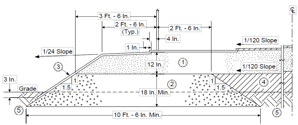
FIGURE 2
CONE - DOWN, GRAVEL RINGWALL, NO MEMBRANE
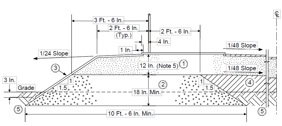
FIGURE 3
CONE–UP, GRAVEL RINGWALL MEMBRANE - ANCHOR SYSTEM 1
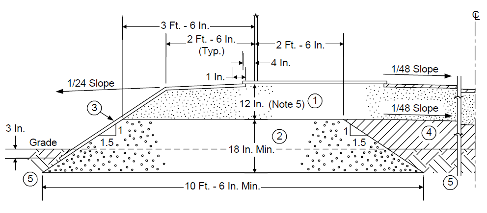
FIGURE 4
CONE - DOWN, GRAVEL RINGWALL MEMBRANE - ANCHOR SYSTEM
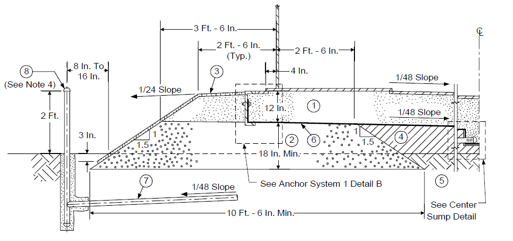
FIGURE 5
CONE–UP, CONCRETE RINGWALL, NO MEMBRANE
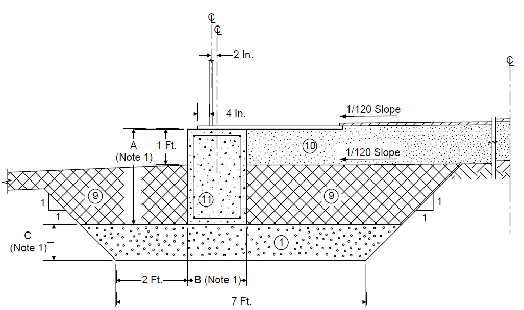
FIGURE 6
CONE–DOWN, CONCRETE RINGWALL, NO MEMBRANE
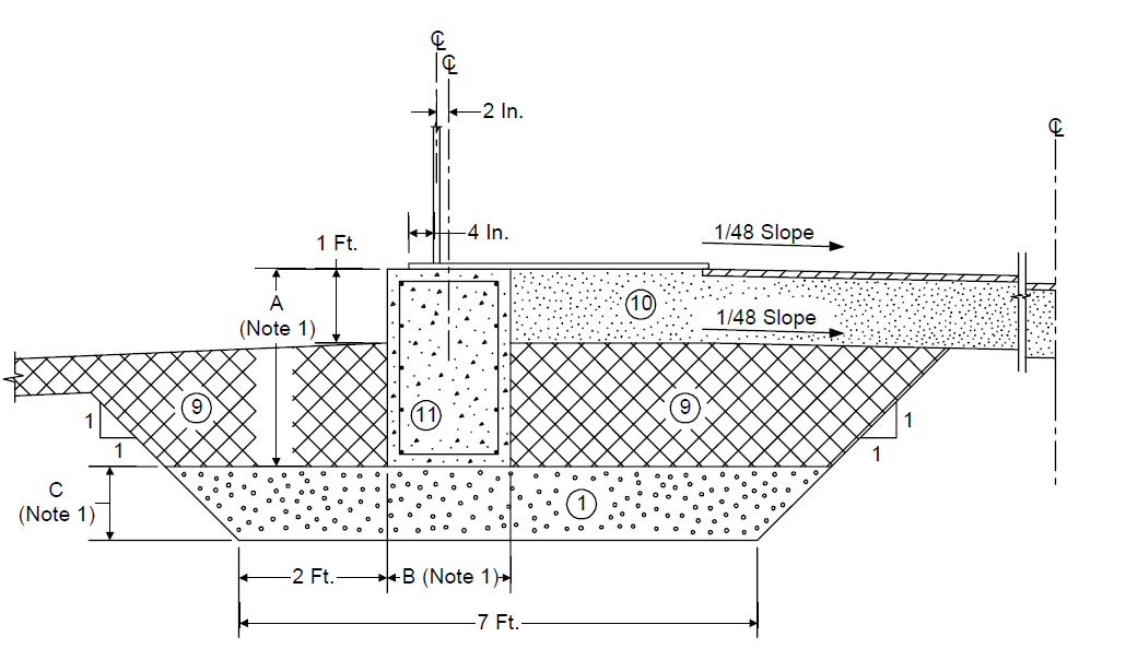
FIGURE 7
CONE–UP, CONCRETE RINGWALL, MEMBRANE - ANCHOR SYSTEM 2
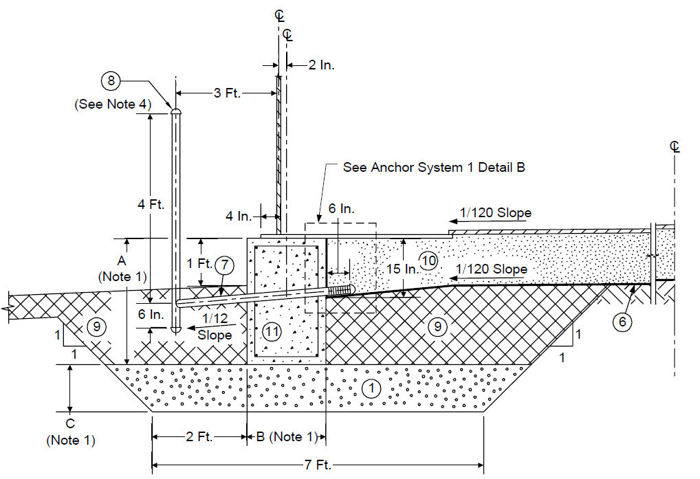
FIGURE 8
CONE–DOWN, CONCRETE RINGWALL MEMBRANE - ANCHOR SYSTEM 3
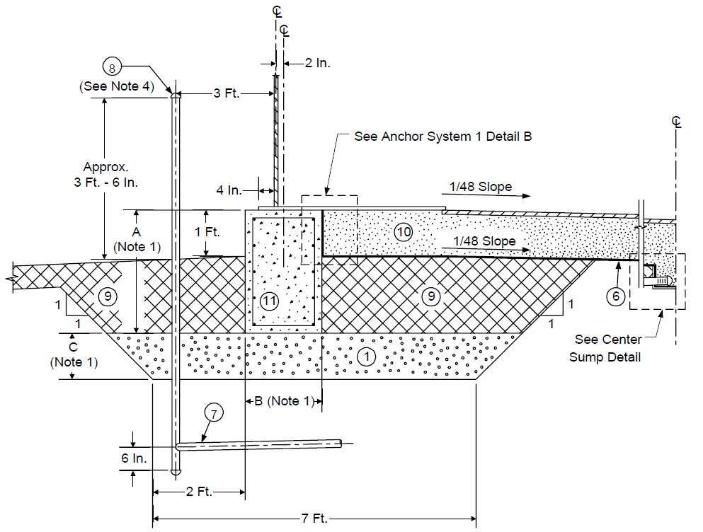
FIGURE 9
CONE–UP, PILES/SLAB, NO MEMBRANE
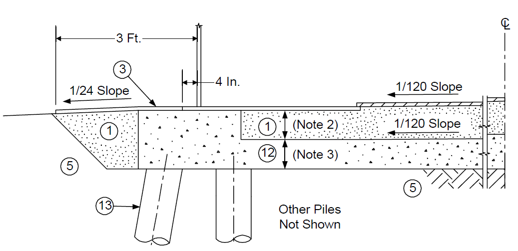
FIGURE 10
CONE - DOWN, PILES/SLAB, NO MEMBRANE
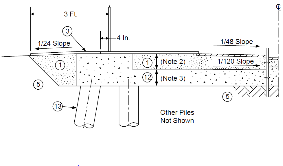
FIGURE 11
CONE–UP, PILES/SLAB, MEMBRANE - ANCHOR SYSTEM 4
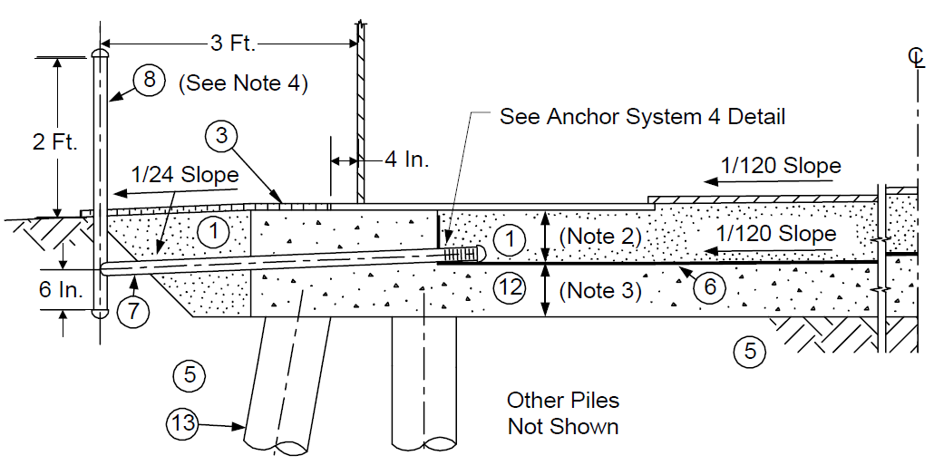
FIGURE 12
CONE - DOWN, PILES/SLAB, MEMBRANE - ANCHOR SYSTEM 4

FIGURE 13
CONE–UP, EARTH PAD, NO MEMBRANE
FIGURE 14
CONE - DOWN, EARTH PAD, NO MEMBRANE
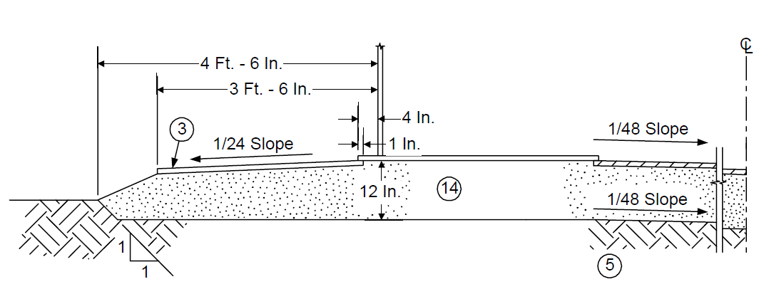
FIGURE 15
CONE–UP, EARTH PAD, MEMBRANE - ANCHOR SYSTEM
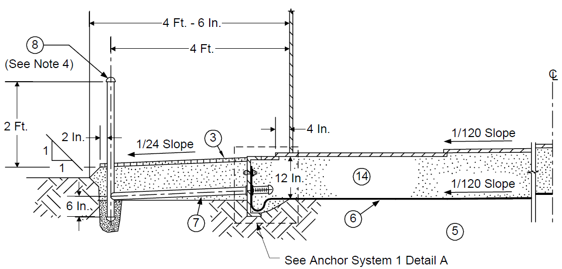
FIGURE 16
CONE - DOWN, EARTH PAD, MEMBRANE - ANCHOR SYSTEM 1
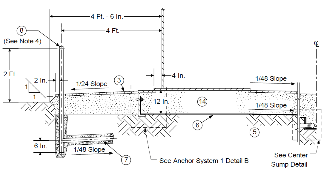
FIGURE 17 ANCHOR SYSTEM 1 DETAILS
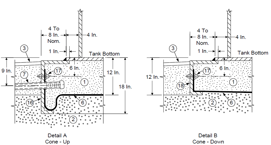
FIGURE 18 ANCHOR SYSTEM 2 DETAIL
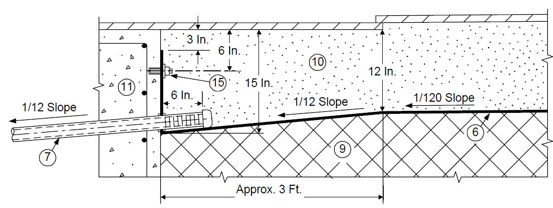
FIGURE 19 ANCHOR SYSTEM 3 DETAIL
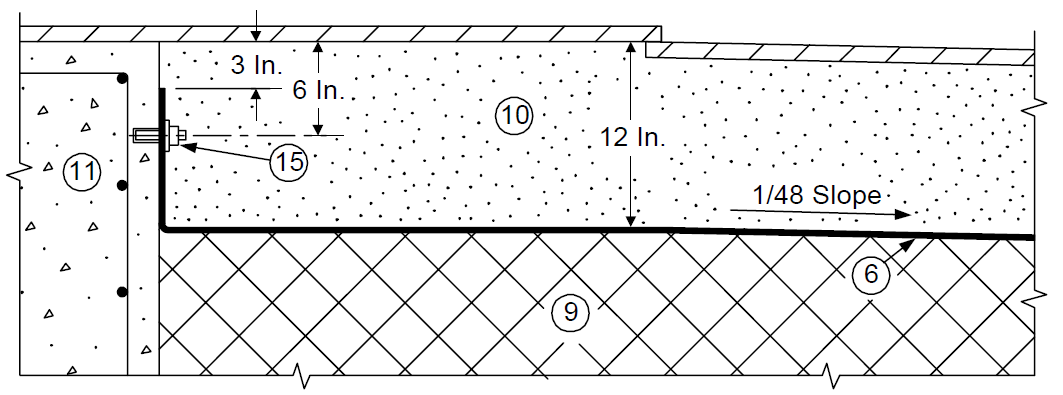
FIGURE 20 ANCHOR SYSTEM 4 DETAIL
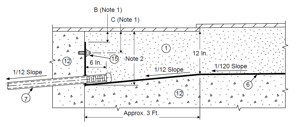
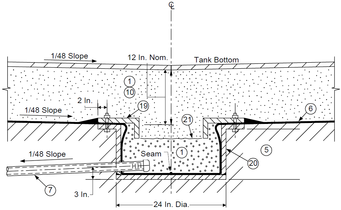
FIGURE 21 CENTER SUMP DETAIL
LEGEND FOR FIGURES 1 THRU 21
LEGEND (Item numbers in circles):
- (*)Clean, dry sand, pea gravel, or well–graded crushed stone or crushed gravel per ASTM D 693. Size Number 6, as specified by the Owner’s Engineer. Size Numbers 7, 56, or 57 are also acceptable, provided the fine grading requirement to meet dimensional tolerances for the tank pad elevations can be met.
- Crushed stone or gravel per Paragraph 6.1.3.
- 1 in. minimum thickness, impermeable sand–asphalt mix (apply after wet test).
- Cohesive or cohesionless fill compacted to densities per Paragraph 6.1.5.
- Undisturbed sub–grade.
- (*)Impermeable membrane, thickness and type to be specified by Owner’s Engineer. Physical properties of the liner shall comply with the requirements of Table 2, as a minimum. Seams are to be tested per EP 4–2–10 Paragraph 8.1.6.
- (*)1-1/2 to 2 in. diameter SCH 40 PVC pipe, slotted and capped at one end, teed into tell–tale pipe at opposite end. Length, actual diameter, slots, expansion loop and spacing to be specified by Owner’s Engineer. Hardware to be specified by Vendor.
- 2 in. diameter SCH 40 PVC tell–tale pipe, capped both ends (top cap removable), teed into 7.
- Clay fill compacted to density per Paragraph 6.1.5.
- (*)12 in. clean, dry sand fill unless otherwise specified.
- (*)Reinforced concrete ringwall - reinforcing steel design to be specified by Owner’s Engineer. Tolerances to comply with API 653.
- (*)Reinforced concrete mat. Reinforcing steel and drainage channels to be specified by Owner’s Engineer.
- (*)Use of piles to be specified by Owner’s Engineer.
- (*)Earth pad per Paragraph 6.1. Height above original grade to be specified by Owner’s Engineer.
- (*)3/8 in. diameter x 3 in. long imbedded anchor - stainless steel - with washer and nut 3/16 in. thick x 2 in. wide continuous stainless steel clamping plate. Anchor spacing to be specified by Owner’s Engineer.
- C. S. channel, angle or plate - continuous with spacer, if required welded to top flange 7/16 in diameter holes required for item 17.
- (*)SS or galvanized studs per item 16 dimensions, with second nut and washer 1/4 in. thick x 2 in wide SS or galvanized clamping plate. Anchor spacing to be specified by Owner’s Engineer. See also Note 6.
- CS channel angle or plate - continuous with spacer, if required, welded to top flange. 7/16 in diameter holes required for item 17.
- (*)Angle 8x4x1/2 CS, with 3/8 in diameter CS bolt, nut and washer, or equivalent. Spacing of holes to be specified by Owner’s Engineer
- 1/2 in. thick CS pan includes angle 4x4x1/2 with holes for 19.
- Geotextile to hold sand, if required.
NOTES TO FIGURES 1 THRU 21
NOTES:
- (*)Dimensions A, B, and C for concrete ringwall designs to be furnished by Owner’s Engineer.
- 3 in. minimum depth of sand between tank bottom and sloped concrete mat over pile foundation.
- (*)Thickness of concrete mat over piles to be specified by Owner’s Engineer.
- (*)If specified by the Owner’s Engineer, tell–tale well pipes shall be eliminated and replaced by a valve, normally closed in service. A concrete manhole, size to be specified by the Owner’s Engineer shall be constructed around the valved end of the leak detection pipe(s).
- 12 in. unless otherwise specified by Owner’s Engineer.
- (*) Embedded polymeric anchors welded to the flexible liner may be used if approved by the Owner’s Engineer.
© 2026 Inflection Point Engineering, LLC. All rights reserved. The content of this page — including calculation methods, reference data, written analysis, interactive tools, and source code — is the intellectual property of Inflection Point Engineering, LLC and is protected under applicable copyright, trademark, and trade secret laws. Unauthorized reproduction, redistribution, modification, or derivative use in whole or in part is prohibited without prior written consent.
Disclaimer. This material is provided for informational and educational purposes only and does not constitute professional engineering advice. Calculations, reference data, and methodologies are based on published standards and accepted engineering practice but are not a substitute for engineering judgment, site-specific analysis, or review by a licensed Professional Engineer. Inflection Point Engineering, LLC makes no warranties, express or implied, regarding the accuracy, completeness, or fitness for a particular purpose of any content presented here, and shall not be liable for any direct, indirect, incidental, or consequential damages arising from its use. Users assume all risk associated with applying this content to real-world design, operations, or decisions.
© 2026 Inflection Point Engineering, LLC. All rights reserved.