 Section 4 — Structures and Foundations
Reinforced Concrete Foundations
IPE Engineering Practice IPE-EP-4-2-3
Document number: IPE-EP-4-2-3 · Section: 4 — Structures and Foundations
SCOPE
- This Practice covers mandatory requirements governing the design of reinforced concrete foundations with bearing either on soil or piles.
- Any deviation to this Practice must be approved by the procedure described in EP 1–1–3.
- An asterisk (*) indicates that a decision or approval by the Owner or the Owner’s Engineer is required, or that additional information is furnished by the Purchaser.
- A revision bar indicates all changes made to this Revision.
- Documentation required for reinforced concrete foundations in accordance with this Practices is given in Table 1.
2.0 REFERENCES
The latest edition of the following standards and publications are referred to herein.
STANDARDS AND PUBLICATIONS
| IPE Engineering Practices |
|---|
| EP 1–1–3 Deviations to IPE Engineering Practices Design EP 4–1–1 Criteria and Loads for Structures EP 4–2–1 Foundation Types and Selection Criteria EP 4–2–8 Support Structures and Foundations for Heavy Machinery EP 4–3–1 Concrete Design EP 10–3–8 Galvanized Coatings |
| ASTM Standards |
| A36 Structural Steel A193 Alloy–Steel and Stainless Steel Bolting Materials for High–Temperature Services A194 Carbon and Alloy Steel Nuts for Bolts for High–Pressure and High–Temperature Service A307 Carbon Steel Externally and Internally Threaded Standard Fasteners A325 High Strength Bolts for Structural Steel Joints, Including Suitable Nuts and Plain Hardened Washers |
| AISC Specification |
| Manual of Steel Construction |
| ACI Standard |
| 318 Building Code Requirements for Reinforced Concrete |
| ICBO |
| Uniform Building Code |
DEFINITIONS
- Contractor - Company or business that agrees to furnish materials or perform specified services at a specified price and/or rate to the Owner.
- Heavy Machinery - Rotating equipment having reciprocating or rotary masses as the major moving parts (such as reciprocating or rotary compressors, pumps, engines, and turbines), and having a gross plan area of more than 20 square feet or a total weight greater than 4,000 pounds.
- Inspector - A Inflection Point Engineering, LLC appointed engineer or inspector.
- Light Machinery - All rotating equipment which is not classified as Heavy Machinery.
- Owner - Inflection Point Engineering, LLC.
- Owner’s Engineer - A Inflection Point Engineering, LLC appointed engineer.
- Purchaser - The party placing a direct purchase order. The purchaser is the Owner’s designated representative.
DESIGN
- Allowable soil bearing pressures shall be based on the results of a soils investigation and a
consideration of permissible total and differential settlements, see EP 4–2–1.
- Footing size and shape shall be determined by settlement considerations, if specified, and by the
following criteria:
- Foundation loads and load combinations shall be in accordance with EP 4–1–1.
- Under the action of vertical or lateral loads, or both, with loading combinations which result in
maximum vertical load or overturning moment, or both, the maximum soil pressure shall not exceed the applicable allowable value.
- Applicable allowable values of bearing pressure for various loading combinations shall be as
specified in the soils investigation report. However, the maximum increase of the basic allowable bearing pressure permitted for loading combinations that include wind, seismic or other occasional loading conditions shall be 33%.
- Foundations shall be designed to have a minimum safety factor of 1.5 against overturning, 1.5
against uplift, and 1.5 against sliding. If wind, rather than seismic load governs, the uplift and sliding factors of safety may be reduced by 15% for the initial erection loadcase, and by 25% for the periodic maintenance loadcase. The safety factor against flotation shall be at least 1.2 against the highest anticipated water level. In determining the safety factor against flotation, allowance should be made for future removal of soil above the foundation or of equipment from it, and for possible loss of skin friction from the sides. No reduction to the flotation or overturning factors of safety is permitted.
- For foundations bearing on cohesionless soil supporting towers or other slender structures with heights greater than 100 ft. (30 m) and a ratio of total height to skirt or base diameter greater than 10: 85% of the foundation shall be in compression for the design overturning moment during erection and 100% of the foundation shall be in compression for the design overturning moment during normal operation. In lieu of these requirements, foundations may be designed based on the factors of safety given in the previous paragraph, provided base shear, uplift and overturning moment are determined from dynamic wind and/or seismic analyses in addition to a consideration of all static loading conditions. In this case, all other requirements in this Section shall be met, except the increase allowed in the basic allowable bearing pressure for occasional loads shall be prohibited.
- Loads and reactions from piping shall be considered in the design of foundations, supports for equipment, and other such structures. Foundations for elevated pipe support shall be designed for a minimum of 20 percent future increase in pipe loadings.
- If not otherwise specified, the maximum permitted long term settlement for foundations shall be
1.0 inch, and the maximum differential, long-term settlement shall be 1/2 inch.
- The bottoms of soil bearing foundations for all major structures and equipment shall be located below the frost line.
- Design of reinforced concrete shall be in accordance with the requirements of this Practice and EP 4–3–1.
- The top of concrete shall be a minimum of 8 inches above finished grade or high point of paving for foundation under the following equipment:
- Steel column bases of open structural framing.
- Pipeway supports.
- Pumps, fans, compressors, and legs or skirts of towers, drums and exchangers.
- For commercial or industrial type buildings, the top of concrete piers shall be flush with the floor.
- As a minimum, piers under base plates and pedestals supporting vessels with skirts shall extend 1–1/2 inch minimum beyond the base plates, or skirt base rings and lugs, in all directions.
- Piers and pedestals shall be reinforced to resist thermal stresses due to expansion of base plates, soleplates, rails, skirt base rings and lugs, anchor bolts, and concrete. The minimum vertical steel for compression members per ACI 318 shall be required. Additionally, as a minimum, vertical reinforcing shall be tied as follows:
- In piers, vertical reinforcing shall be enclosed in lateral ties per ACI 318 requirements for tie reinforcement for compression members.
- In pedestals, vertical reinforcing shall be enclosed by complete circumferential ties meeting the size and spacing requirements of ACI 318 for tie reinforcement for compression members.
- The spacing between the top two ties in piers and pedestals shall not exceed 4 inches.
- Concrete in piers and pedestals, and grout under base plates, soleplates, rails, skirt base rings and lugs, shall not extend above the bottom face of these structural support components.
- (*)If required by the Owner’s Engineer, pedestals for vessels with skirts shall have the area within the skirt sloped for drainage, and a suitable embedded pipe or opening in the grout provided, discharging to the pavement outside the skirt.
- At least 3 inches of concrete protection shall be provided between the outside diameter of the anchor bolt sleeve and the soil–contact surface of the concrete. Anchor bolts shall be located inside the reinforcing steel cage.
- (*)Small equipment and pipe base supports with loads less than 1000 lbs., and stair and ladder pads shall be supported on reinforced concrete paving or floor slabs. Small equipment and pipe base supports with loads greater than 1000 lbs. may be supported on reinforced concrete paving or floor slabs when the design is shown to be acceptable by analysis. In such cases, the Owner’s Engineer shall review the results of the analysis and approve the subsequent design. In unpaved areas, these items shall be supported on concrete pads with a minimum embedment depth below the frost line.
- (*)Concrete foundation members shall be isolated from adjacent equipment slabs, or pavements using joint filler and sealer, unless otherwise specified by the Owner’s Engineer. The sealer shall be a two component polysulfide component, unless otherwise specified by the Owner’s Engineer.
- (*)Foundation design calculations and input and output from any computer analyses performed in the foundation design process, shall be submitted to the Owner’s Engineer for review.
- (*)Final construction drawings shall be reviewed and approved by a registered Professional Engineer, and submitted to the Owner’s Engineer.
ANCHOR BOLTS
- Anchor bolts shall be designed to resist all conditions of tension and shear at the base of structures, including the tension effects of any bending moments which may result from fixation.
- Anchor bolts shall be sized using allowable stresses given in the AISC Specification, however, no increase in allowable stresses shall be taken when wind or earthquakes are considered. Anchor bolt sizes determined by this method shall have their diameters increased by 1/8 inch as a corrosion allowance. The embedment depth and loads transferred to the concrete shall be evaluated based on ACI provisions.
- Anchor bolts shall have a minimum clearance of 3 inches from the faces of piers or foundation blocks.
- Material for carbon steel anchor bolts shall be ASTM A 36 unless otherwise specified. Material of nuts for carbon steel anchor bolts shall be per ASTM A 307, Grade B, hexagon, heavy series, or ASTM A 325, Type 3.
- Material for alloy steel anchor bolts shall be per ASTM A 193, Grade B7 or in accordance with Table 1 (Page 1–5) of the ASIC Manual of Steel Construction. Material of nuts for alloy steel anchor bolts shall be per ASTM A 194, Grade 2H.
- Alloy bolting material with a washer and two nuts shall be used when anchoring reciprocating compressors and other equipment subject to severe vibration.
- (*)If difficulty is expected in maintaining anchor bolt alignment, sleeves shall be specified. Unless otherwise approved by the Owner’s Engineer, sleeves shall not be used with bolts larger than 1–1/2 inches in diameter or when multiple anchor bolts are required in a small area. Templates shall be used for such bolts. Generally, sleeves are not used for anchor bolts for column base plates.
- When protective coatings are required for anchor bolts, they shall be galvanized per EP 10–3– 8.
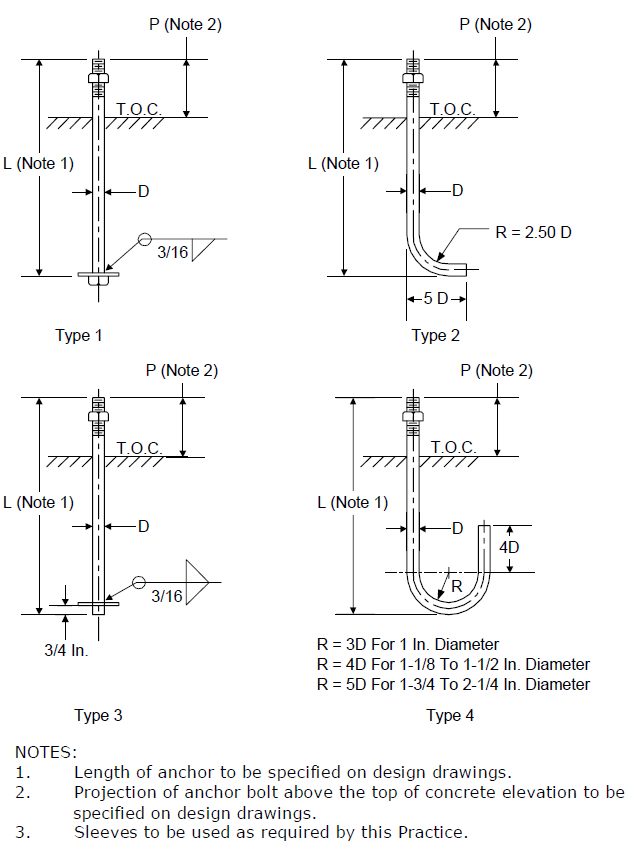
- (*)Acceptable anchor bolt details are given in Figure 5. Alternate designs shall be submitted to the Owner’s Engineer for approval. As–built plan, elevation and detail drawings of anchor bolt placement and design shall be submitted to the Owner’s Engineer.
ADDITIONAL REQUIREMENTS FOR LIGHT MACHINERY
- The ratio of concrete foundation weight to equipment weight shall be as follows:
- Rotary Equipment - 3:1.
- Reciprocating Equipment - 5:1.
- (*)Typical pump foundation and pump slab details are shown in Figure 1 and Figure 2. Piping elbow supports located adjacent to the pump and driver shall rest on a concrete base that is integral with the equipment foundation. Details of the base shall be shown on foundation drawings per Figure 3. Pump slabs shall be provided with wash down facilities when specified by Owner’s Engineer.
- In addition to reinforcing steel required by design, a minimum of two rows of ties around tops of anchor bolts in the pump pedestal and temperature steel in the top of the slab shall be provided.
- On pump slabs, the pump foundations may be an integral part of the slab. When this is done, the mass ratio shall be computed as the ratio of the weight of the entire pump slab to the combined weight of the equipment.
- (*)Pump slabs shall be provided with drains to catch basins, which shall be located at the edge of the slab. The slab shall be sloped to drain spills away from the pumps. Individual drains are required for all pumps handling flammables and shall be piped to a catch basin or manhole under seal. If the pump base plate is not provided with a drip pan, a two by four–inch nominal slot shall be provided around the pump pedestal sloped to an open hub as shown in Figure 4. Drain trenches and pipe trenches are not permitted unless approved by Owner.
- Electrical conduits shall be provided to the pump foundation before the slab is poured.
7.0 ADDITIONAL REQUIREMENTS FOR HEAVY MACHINERY
Additional requirements for heavy machinery are covered in EP 4–2–8.
8.0 TABLES
TABLE 1 DOCUMENTATION REQUIREMENTS
FOR REINFORCED CONCRETE FOUNDATIONS PER EP 4–2–3
| Item | Description | Format | As–Built |
|---|---|---|---|
| 1 | Calculations and computer input/output performed in the foundation design process. | Text | N/A |
| 2 | Plan, elevation and section drawings of foundation. | CALS G4 TIFF (Compressed) |
N/A |
| 3 | Plan, elevation and detail drawings of anchor bolt placement. | CALS G4 TIFF (Compressed) |
N/A |
9.0 FIGURES
FIGURE 1 PUMP FOUNDATION
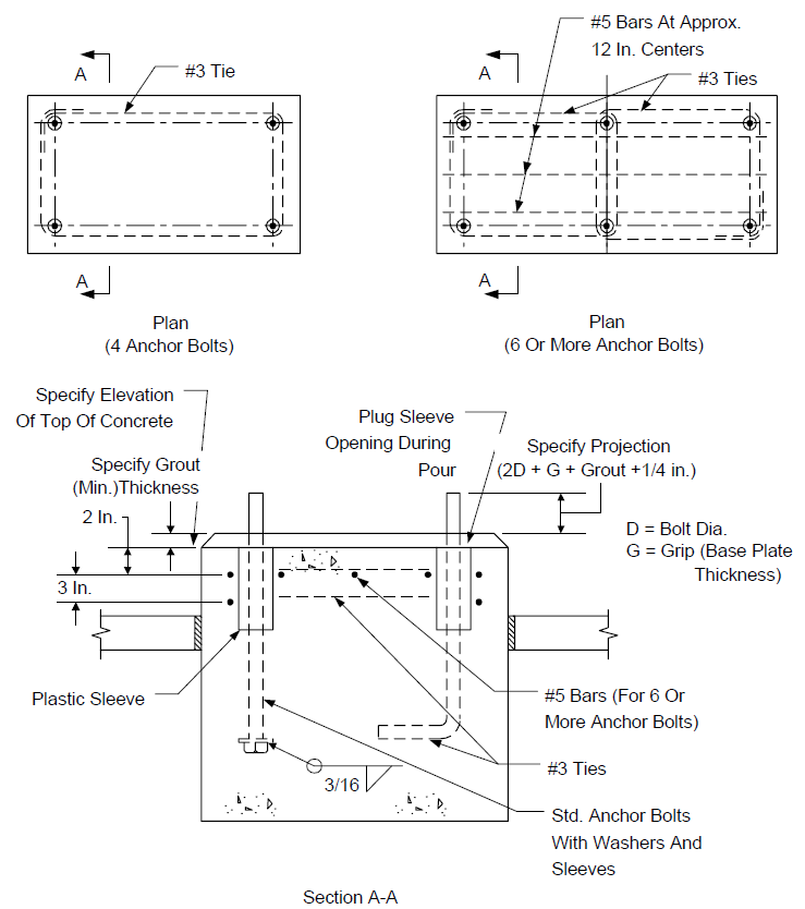
FIGURE 2 PUMP SLAB
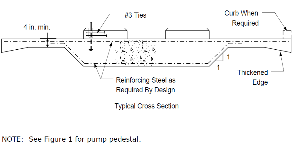
FIGURE 3
PUMP FOUNDATION WITH INTEGRAL PIPE SUPPORT BASE
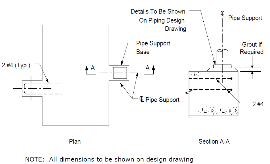
FIGURE 4 PUMP BASE DRAINS
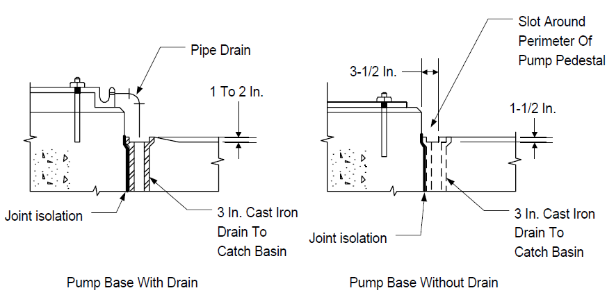
FIGURE 5
TYPICAL ANCHOR BOLT DETAILS
© 2026 Inflection Point Engineering, LLC. All rights reserved. The content of this page — including calculation methods, reference data, written analysis, interactive tools, and source code — is the intellectual property of Inflection Point Engineering, LLC and is protected under applicable copyright, trademark, and trade secret laws. Unauthorized reproduction, redistribution, modification, or derivative use in whole or in part is prohibited without prior written consent.
Disclaimer. This material is provided for informational and educational purposes only and does not constitute professional engineering advice. Calculations, reference data, and methodologies are based on published standards and accepted engineering practice but are not a substitute for engineering judgment, site-specific analysis, or review by a licensed Professional Engineer. Inflection Point Engineering, LLC makes no warranties, express or implied, regarding the accuracy, completeness, or fitness for a particular purpose of any content presented here, and shall not be liable for any direct, indirect, incidental, or consequential damages arising from its use. Users assume all risk associated with applying this content to real-world design, operations, or decisions.
© 2026 Inflection Point Engineering, LLC. All rights reserved.