 Section 4 — Structures and Foundations
Atmospheric Storage Tank Foundation Monitoring, Repair and Retrofit
IPE Engineering Practice IPE-EP-4-2-10
Document number: IPE-EP-4-2-10 · Section: 4 — Structures and Foundations
Figure 8 Tank Bottom Bulges And Depressions 27Figure 8 Tank Bottom Bulges And Depressions 27
Figure 9 Cone-Up, Earth Pad, Double Bottom 28
Figure 10 Cone-Down, Earth Pad, Double Bottom 29
Figure 11 Cone-Up, Gravel Ringwall Double Bottom 30
Figure 12 Cone-Down, Gravel Ringwall Double Bottom* 31
Figure 13 Cone-Up, Concrete Ringwall Double Bottom 32
Figure 14 Cone-Down Concrete Ringwall Double Bottom 33
Figure 15 Cone-Up, Piles/Mat, Double Bottom 34
Figure 16 Cone-Down, Piles/Mat, Double Bottom 35
Figure 17 Center Sump Detail 36
Figure 1`8 Double Bottom Liner Attachment 37
SCOPE
- This Practice covers mandatory requirements for the repair and retrofit of foundations of existing atmospheric storage tanks. Tanks covered by this Practice include those built in accordance with API Standard 650 and its predecessor 12C.
- The scope of this Practice includes repairs and retrofits made on tank foundations, repairs and replacement of subgrade, use of double tank bottoms, leak detection and prevention systems, and tank bottom relevelling.
- The requirements for lifting atmospheric storage tanks, tank shell relevelling and tank floating are covered in EP 9-1-6.
- The requirements for repairs and retrofits to tank bottoms, shells, and roofs are covered in EP 9-1-5.
- A revision bar indicates all changes made to this Practice.
- Any deviation from this Practice must be approved by the procedures described in EP 1-1-3 .
- An asterisk (*) indicates that a decision or approval by the Owner or Owner's Engineer is required, or that additional information is furnished by the Purchaser.
- Documentation required for tank foundations in accordance with this Practice is given in Table 3.
2.0 REFERENCES
The latest edition of the following standards and publications are referred to herein.
STANDARDS AND PUBLICATIONS
STANDARDS AND PUBLICATIONS (CONTINUED)
| API Standards |
|---|
| RP 651 Cathodic Protection of Aboveground Petroleum Storage Tanks Std 650 Welded Steel Tanks for Oil Storage Std 653 Tank Inspection, Repair, Alteration and Reconstruction |
| ASME Codes |
| Sec VIIIPressure Vessels, Alternative Rules, Division 2 |
| ASTM Standards |
| D471 Rubber Property - Effect of Liquids D638 Tensile Properties of Plastics D751 Standard Test Methods for Coated Fabrics D1004 Initial Tear Resistance of Plastic Film and Sheeting D1204 Linear Dimensional Changes of Nonrigid Thermoplastic Sheeting or Film at Elevated Temperature D2136 Standard Test Methods for Coated Fabrics-Low-Temperature Bend Test |
DEFINITIONS
- Contractor - Company or business that agrees to furnish materials or perform specified services at a specified price and/or rate to the Owner.
- Earth Pad - The soil used to elevate tank above surface grade.
- Inspector - A Inflection Point Engineering, LLC appointed engineer or inspector.
- Jacking - Procedure whereby a portion of or an entire tank shell is lifted to a height sufficient to permit relevelling of the tank shell or minor repairs to the foundation. Typically, hydraulic jacks are used, and lift points are lugs welded to the external surface of the tank shell near the bottom.
- Mud Jacking - Relevelling process whereby a rigid floor or slab is brought to a prescribed elevation using a sand/cement mixture injected beneath the floor or slab.
- Owner - Inflection Point Engineering, LLC.
- Owner's Engineer - A Inflection Point Engineering, LLC appointed engineer.
- Pile - Structural member of timber, concrete, and/or steel, used to transmit surface loads to lower levels in the soil mass.
- Pressure Grouting - Local tank bottom relevelling procedure whereby a Portland cement grout is injected through nozzles welded in a tank bottom to bring the area to a prescribed elevation or to fill voids.
- Relevelling - Procedure whereby a portion of or an entire tank shell and/or bottom is/are brought to a prescribed elevation using jacking and placement of fill, or using pressure injection of Portland cement grout.
- Ringwall - Foundation provided under the shell to minimize shell settlement caused by the shell cutting into the soil.
- Tank Lifting - Procedure whereby an above ground storage tank is lifted to a sufficient height for human access to the entire tank bottom and foundation for repairs or retrofit. Typically, the tank will be lifted to a height of seven feet or more above grade.
SETTLEMENT MONITORING
- Site and Tank Bottom Survey Locations
- Tank site and bottom surveys shall be performed and results reported on the Tank Settlement Data Sheet, EP 4-2-10DS.
- Tank site and bottom elevation readings shall be taken at locations for which settlement history exists. Additional measurements shall be taken, as needed, to comply with the requirements of this Practice.
- Elevation readings shall be taken with a transit at a minimum of eight equally spaced benchmark points around the base of the tank at least three feet above grade, see Figure 1 for other spacing requirements. The first seam may be used for this purpose.
- The slope of the grade immediately around the outside of the tank shall be noted and potential or actual ponding problems shall be indicated.
- The difference in elevation between the tank base elevations and the general grade elevation surrounding the tank, D, shall be determined, see Figure 2.
- Elevation readings shall be taken at a minimum of eight equal-spaced radii along the bottom. If the tank diameter is less than 80 feet, elevation readings shall be taken at a minimum of four equal-spaced points along each radii. The maximum spacing of readings along a radius shall not exceed ten feet. If an annular plate is present, three equal-spaced readings shall be taken along each radii projected onto the annular plate, see Figure 3.
- (*)When edge-cutting settlement is indicated, additional readings shall be taken on one-foot intervals, or less, along each radii for the first ten feet in from the tank shell. Closer spacing may be specified by the Owner's Engineers, see Figure 3.
- Settlement Measurement Frequency
- Shell settlement measurements shall be taken during initial hydrotest and shell and bottom settlement measurements shall be taken after initial hydrotest based on the requirements of EP 9-1-1.
- External settlement measurements shall be taken at least every two years for existing tanks on earth pads and gravel ringwalls, and at least every four years for existing tanks on concrete ringwalls, piles and caissons. External settlement measurements shall also be taken when formal external inspections specified by API 653 are performed, or as required by Paragraph 4.3.5.
- Internal settlement measurements shall be taken for existing tanks when formal internal inspections specified in EP 15-4-4 are performed, or as required by Paragraph 4.3.5.
- Settlement History Calculations
- Settlement calculations given in this Practice shall be performed after each recording of settlement data. These calculations shall be documented in the tank's permanent records.
- The settlement of each data point shall be plotted versus location on the shell, similar to Figure 4, as required by this Practice. Additionally, a Time Settlement History shall be constructed, see Figure 5.
- For each settlement point, the current rate of change of settlement shall be calculated. This rate shall be used to determine the expected settlements for each point at the time of the next scheduled settlement measurements.
- If the expected settlements calculated exceed the permissible values in this Practice, calculations shall be performed, using the current rate of change of settlement, to determine the times at which expected settlements (uniform, planar, differential) equal the corresponding permissible settlements.
- The minimum time determined in the previous paragraph shall be used to establish a new settlement measurement frequency. The next settlement measurements shall be taken before one-half the time determined per this paragraph has elapsed, and shall continue at this frequency until the actual settlements have exceeded permissible values at which time an evaluation of whether or not repairs are required shall be performed in accordance with Section 5.0.
- Settlement Measurement Record Keeping
- Tank shell and bottom settlement measurements shall be recorded on a Tank Foundation Settlement Data Sheet, EP 4-2-10DS. All Tank Foundation Settlement Data Sheets shall be kept as part of the permanent records for the tank.
- Locations of settlement data points shall be recorded on the Settlement Data Point Locations plot, see Figure 6, and shall be attached to the Tank Foundation Settlement Data Sheet, EP 4- 2-10DS.
- Calculations required per Section 4.0 and Section 5.0 shall be attached to the Tank Foundation Settlement Data Sheet, EP 4-2-10 DS
- For each settlement data period, one tank shell settlement plot, see Figure 4, shall be constructed and maintained as part of the permanent records for the tank. Additionally, one Time-Settlement History, see Figure 5, containing the minimum, maximum and average settlement as a function of time, shall be constructed and maintained as part of the permanent records for the tank.
EXISTING TANK FOUNDATION EVALUATION
- General Foundation Evaluation Requirements
- The need for tank foundation repair or retrofit shall be evaluated if inspection indicates that any of the following have occurred:
- Tank shell distortions, roof distortions or roof binding indicative of excessive settlements.
- Failures of the foundation earth pad, ring wall, piles or concrete mat, including, but not limited to, erosion of soil or gravel, concrete spalling or structural cracking, reinforcement or anchor bolt excessive corrosion, distortion or failure.
- Dead spots, defined as areas of the tank bottom which are not in contact with grade when the tank is empty, in the tank bottom.
- Drainage problems around the tank.
- The need for tank foundation repair or retrofit shall be evaluated if service condition changes that affect foundation loads are to be made, including, but not limited to, an increase in fill height, addition of a shell course, change in product, or change to operation at a temperature above 200°F.
- The need for tank foundation repair or retrofit shall be evaluated if shell or roof modifications are to be made.
- The evaluation of existing tank foundations shall include:
- A review of tank service history including previous repairs and modifications.
- Internal and external inspection of the tank.
- A topographical survey of the site surrounding the tank per Paragraph 4.1.
- A survey of tank bottom elevations per Section 4.0.
- An analysis of settlement data per Paragraph 5.2.
- (*)analysis of soil conditions, including soil borings conducted in accordance with EP 4-2-7, and any other tests specified by the Owner's Engineer.
- Estimates of future settlement per Paragraph 5.2 and Section 4.0.
- An evaluation of tank floor deformations per Paragraph 5.2.
- Permissible Settlements
- (*)Tank foundation repair or retrofit shall be required if any of the following maximum permissible settlements has been exceeded. Alternatively, if approved by the Owner's Engineer, a more rigorous analysis, performed in accordance with Section 10.0, can be used to determine the adequacy of the existing foundation:
- Uniform settlement of sufficient magnitude to overstress piping connections, or to produce ponding of water against the lower shell course. Ponding, however, can be avoided by proper grading of the foundation. Additionally, piping can be re-located to reduce piping stresses.
- Planar tilt of sufficient magnitude to produce a liquid level increase and corresponding hoop stresses exceeding API 650 allowable stress values, or of sufficient magnitude to bind peripheral seals on floating roofs.
- Maximum differential settlement, S, determined in accordance with Appendix B of API 653, see Figure 4 in excess of:
S deflection (out of plane) , feet
L arc length between measurement points, feet Y yield strength, psi
E Young' s modulus, psi H tank height, feet
- Maximum edge cutting settlement, B, in accordance with the 1998 addendum (or later) of API 653.
- (*)Tank foundation repair or retrofit shall be required if following maximum permissible tank bottom bulge or depression has been exceeded. Alternatively, if approved by the Owner's Engineer, a more rigorous analysis, performed in accordance with Section 10.0, can be used to determine the adequacy of the existing foundation, see Figure 8:
B 0.37R
where:
B height of bulge or despression (max),inches
R radius of inscribed circle in bulge or depressed area,feett
- Tank Lift Decision
- (*)Unless otherwise required by the Owner's Engineer, the following tank foundation repairs or retrofits shall be made with the tank in place:
- Replacement of an entire tank bottom using the double bottom approach per EP 9-1-5.
- Retrofit of existing tanks with leak detection and containment systems, using the double bottom approach.
- Relevelling of a tank exceeding permissible settlement values.
- Repair of spalling and cracked concrete.
- Repairs of partial washouts or erosion of foundation materials at the periphery of the tank.
- Repairs to bulges or depressions in the tank bottom.
- Repairs to dead spots under tank bottoms.
- A tank lift for repair or retrofit shall be required in the following circumstances:
- Soil improvement and re-grading of the tank site is required because of excessive settlements.
- Tank foundation replacement is required because of foundation failure.
- Tank foundation replacement is required because of a change in service or tank modifications.
- Tank foundation replacement is required because edge cutting settlement exceeding the permissible value has occurred.
- Extensive amounts of contaminated soil must be removed from beneath a tank.
- A cost-benefit analysis indicates it is desirable to lift a tank to perform major tank bottom repairs.
- Repairs of pile foundations.
- Tank lifting, shell relevelling and floating requirements are given in EP 9-1-6.
FOUNDATION REPAIR/RETROFIT WITHOUT TANK LIFT
- Partial Tank Shell Relevelling
Where partial tank shell relevelling is required because of excessive settlements, jacking against external shell lugs shall be used. Shell relevelling shall be performed in accordance with EP 9-1-6.
- Partial Tank Bottom Relevelling
- (*)Where less than twenty percent of a tank bottom requires relevelling, pressure injection of Portland cement grout shall be used, unless otherwise specified by the Owner's Engineer.
- (*)Specifications for Portland cement grout material used for tank bottom relevelling shall be submitted to be to the Owner's Engineer for approval. Grout shall be properly conditioned, mixed and placed in accordance with EP 4-2-9.
- The procedure for tank bottom relevelling shall be as follows:
- Shell relevelling and ringwall repairs shall be completed prior to pressure grouting, in order to form a stop at the periphery of the shell.
- (*)Injection nozzles, 1-1/2 to 3 inch nominal diameter, shall be welded in the bottom plates with a center to center spacing not to exceed 10 feet. On floating roof tanks, nozzles shall be located near roof support legs; however, in no case shall injection nozzles be closer than 12 inches from existing weld seams. Actual location plans for injection nozzles shall be approved by the Owner's Engineer.
- (*)When required, temporary supports shall be installed through openings in the tank bottom to unload floating roof support legs. The design for temporary supports shall be approved by the Owner's Engineer.
- Pressure injection of the grout shall be done under close supervision and careful inspection. It may be necessary to cut inspection holes between grout injection nozzles to insure uniform disbursement of the material. Injection of grout shall continue until the specified distribution has been obtained.
- The grout manufacturer's recommendations for cure shall be followed.
- After the required initial set has occurred, temporary roof supports shall be removed, and temporary support, injection and inspection holes shall be patched with the material matching the existing bottom tank material. Patch welding shall comply with API 653 and EP 9-1-2.
- Internal liner material that was removed or damaged shall be repaired per EP 10-3-7.
- (*)In cases where more than twenty percent of the tank bottom requires relevelling, an economic comparison shall be made between pressure injection of grout, tank lifting and relevelling, and removal of affected bottom plates and local repair of subgrade. Documentation of this evaluation shall be submitted to the Owner's Engineer for review.
- (*)Mud jacking repairs may be performed if approved by the Owner's Engineer. Details for the mud jacking procedure and a material specification shall be submitted for approval.
- External Foundation Repair
- (*)Localized concrete and gravel ringwall repairs shall be performed with the tank in place or with localized jacking done in accordance with EP 9-1-6. Major ringwall repair or replacement may require tank lifting. The Owner's Engineer shall approve the method of ringwall repair.
- Materials for ringwall repair shall comply with Figure 21 of EP 4-2-7. Details of the ringwall repair material and procedures shall be submitted to the Owner's Engineer.
- Grading to improve drainage shall be performed with the tank in place unless more extensive foundation repairs are required. Earthwork within three feet of the tank shell or gravel ringwall shall be performed using hand tools. Heavy machinery shall not be used within this area. Precautions shall be taken to avoid damage to concrete foundations when grading is required.
- Double Tank Bottom Retrofits
- Tanks requiring complete bottom replacement shall be evaluated to determine whether they shall be retrofitted in place with a second bottom installed through a slot in the shell in accordance with EP 9-1-5 or lifted and retrofitted with a new bottom.
- In cases where leak detection and release prevention barriers are to be added to existing tanks that do not require other repairs, an evaluation shall be made to determine whether a tank lift retrofit or double bottom retrofit shall be used. Tank lift retrofits shall be performed in accordance with Section 7.0.
- Double tank bottom designs shall comply with the requirements of this Practice and EP 9-1-5.
- Double bottom details are given in Figure 7 through Figure 18. Table 1 shall be used to determine slot height, allowable tolerances on slotting, and fill material for double bottom retrofits.
- (*)Plan, elevation and detail drawings required for double bottom retrofits shall be submitted to the Owner's Engineer.
- Anchor Bolt Repairs
- (*)Failed, deformed or severely corroded anchor bolts shall be replaced with self-drilling anchors approved by the Owner's Engineer.
- If possible, existing anchor bolts shall be removed from the tank foundation and larger diameter self-drilling anchor bolts shall be installed in the existing anchor locations.
- If it is not possible to locate replacement anchor bolts at existing anchor locations, chair assemblies shall be relocated adjacent to their initial position and self-drilling anchor bolts equal in size to the original anchor bolts shall be installed at the new chair locations.
- If required, chair assemblies shall be repaired with material identical to the original chair assembly material.
- Concrete damage, including damage to reinforcement, shall be removed and replaced. The compressive strength of replacement concrete shall be a minimum of 3000 psi at 28 days. Concrete and reinforcement materials shall comply with EP 4-3-1.
- Adequate anchoring of replaced reinforcement shall be provided by grouting new reinforcement in to existing concrete. Materials for grouting shall comply with EP 4-2-9.
FOUNDATION REPAIR/RETROFIT WITH TANK LIFT
- Procedures for tank lifting shall comply with the requirements of EP 9-1-6.
- (*)Lifted tank foundation repair and retrofit details shall comply with Figures 3 through 6, Figures 9, 10, 13, 14, and 17 through 21 of EP 4-2-7. Plan, elevation and detail drawings required for the repair or retrofit shall be submitted to the Owner's Engineer.
- Lifted tanks requiring soil improvement or removal of contaminated soil shall be retrofitted and brought back to the prescribed elevation, sufficient to prevent ponding around the tank, using soils that comply with EP 4-2-7.
LEAK DETECTION. RELEASE PREVENTION AND CATHODIC PROTECTION
- Leak Detection and Release Prevention Barrier Systems
- Tanks retrofitted with double bottoms shall have leak detection and release prevention barrier systems per details given in Figures 9 through Figure 18.
- (*)Lifted tanks shall be retrofitted with a leak detection and release prevention barrier system per details given in Figures 3 through 6, 9, 10, 13, 14, and 17 through 28 of EP 4-2-7. Plan, elevation and detail drawings required for leak detection and release prevention retrofit shall be submitted to the Owner's Engineer.
- Materials for liners shall satisfy the requirements given in Table 2 and API 650 Appendix I. In cases of conflict, the more stringent requirements shall apply.
- Zipper-type liner seams shall not be used.
- (*)Spray-on urethane liner systems may be used, if approved by the Owner's Engineer.
- (*)All leak detection and release prevention liner systems shall have seams leak tested. Shop- seamed liners may be leak tested in the factory, provided the Owner is notified at least 7 days prior to testing. Field seams shall be 100% vacuum box tested. All liner penetrations shall be tested for leaks. Liner penetration leak testing methods shall be approved by the Owner's Engineer. Results of field tests shall be recorded on EP 4-2-10C or an alternative format acceptable to the Owner's Engineer.
- (*)The liner shall be placed directly on the old tank bottom, if one exists, or on the prepared subgrade, unless otherwise specified by the Owner's Engineer. The use of geotextiles or other preparatory surfaces shall be specified by the Owner's Engineer.
8.2 Cathodic Protection Systems
Cathodic protection systems shall be designed in accordance with EP 10-3-6.
PAINTING, INTERNAL LINING AND COATING
- All painting required as a result of tank foundation repair and retrofit shall be in accordance with EP 10-3-1.
- (*)All internal coatings and linings that are required as a result of tank foundation repair and retrofit shall be in accordance with EP 10-3-7. Coating and lining materials shall be approved by the Owner's Engineer.
ALTERNATIVE SETTLEMENT ANALYSIS REQUIREMENTS
- General Analysis Requirements
- When specified, more rigorous analyses can be substituted for the equations used in determining allowable settlements in accordance with this Practice.
- The finite element method shall be used to perform alternative settlement analyses.
- The tank bottom profile used in performing the settlement analyses shall be based on field measurements taken during the most recent internal inspection and settlement survey in accordance with the requirements.
- (*)Finite element model input and results shall be submitted to the Owner's Engineer for review.
- Finite Element Modeling Requirements
- Tank shell, fixed roof and tank bottom structures shall be modeled using two-dimensional or three-dimensional axisymmetric or shell elements with large strain, large rotation, and elastic/plastic material property capabilities.
- When required, tank foundation structures and materials shall be model led using two or three- dimensional elements, compatible with the elements used for the tank structures.
- Soils shall be modeled using elasticity, porous elasticity, or clay plasticity material properties, where appropriate. Subgrade materials shall not be capable of developing tensile stresses. Material properties for soils in a finite element model shall be determined by a geotechnical engineer, based on data from soils investigations done at the tank site.
- When modeled, the subgrade shall be modeled a minimum distance of one-half the tank's radius beyond the tank shell centerline, and a minimum depth beneath the tank bottom, at the tank bottom low point, equal to the tank's radius, unless bedrock occurs at a higher elevation as determined by a soils investigation.
- When modeled, cohesive subgrade in contact with tank bottoms, tank shells and other buried steel structures shall be modeled using interface elements with a coefficient of friction of 0.35.
- When modeled, cohesive subgrade in contact with buried concrete shall be modeled using interface elements with a coefficient of friction of 0.45.
- (*)When modeled, cohesionless soil in contact with buried structures shall be modeled using interface elements with a coefficient of friction of 0.15, unless otherwise specified by the Owner's Engineer.
- Gaps beneath the tank bottom and subgrade in the un-filled condition shall be included in the finite element model. The extent of non-contact and the depth of the gap shall be estimated during the internal tank bottom settlement survey.
- Where appropriate, the finite element model of tank settlement shall consider groundwater and pore pressure effects.
- Finite Element Analysis Requirements
- Where appropriate, finite element analyses of settlement shall consider loads due to overburden, tank shell and bottom dead loads, the greater of the full fluid weight or full hydrostatic weight, and roof dead and live loads.
- For tanks with floating roofs, the roof loads shall be included in the uniformly distributed fluid pressure on the tank bottom.
- For tanks with fixed roofs, the roof and internal supporting members shall be modeled or boundary conditions and loads shall be applied at the top of the shell to model roof loads and the restraint the roof places on the shell, and concentrated loads shall be placed on the tank bottom at locations of support columns. The distribution of roof weight between the shell and support columns shall be based on the principles of statics.
- (*)Where appropriate, thermal expansion of the tank shall be considered in the analyses. The boundary conditions for the thermal expansion case shall be determined from a heat transfer analysis of the tank and subgrade, and shall be submitted to the Owner's Engineer for review and approval.
- (*)If required by the Owner's Engineer, tank bottom's not in contact with subgrade in the un- filled condition shall be modeled with tank filling loads added incrementally to determine the fill height at which the entire tank bottom is in contact with the subgrade.
- (*)The finite element program and modeling techniques utilized shall have the capability to include seismic effects, via response spectra analyses, if specified by the Owner's Engineer.
- Permissible Stresses due to Settlements
- Bearing stresses at any point in the subgrade shall not exceed one half the ultimate bearing capacity of the soils under the most stringent combination of loads and settlement.
- Primary and secondary stresses in the tank shell, roof and bottom shall not exceed allowable stresses given in ASME Boiler and Pressure Vessel Code Section VIII Division 2 Appendix 4.
- If the tank being analyzed is thermally cycled more than 100 times per year, on average, a fatigue analysis shall be performed in accordance with ASME Boiler and Pressure Vessel Code Section VIII Division 2 Appendix 5.
- If the tank being analyzed experiences fill height changes resulting in a lower fluid level less than the fluid height determined in Paragraph 10.3.5, more frequently than 100 times per year, on average, fatigue analysis shall be performed in accordance with ASME Boiler and Pressure Vessel Code Section VIII Division 2 Appendix 5.
HYDROTEST REQUIREMENTS
- Except as otherwise noted in this Practice, a full hydrostatic test shall be performed after all tank foundation repairs and retrofits and any tank repairs and alterations requiring a hydrotest in accordance with EP 9-1-5 have been completed.
- (*)Unless otherwise specified by the Owner, a full hydrotest shall not be required when tank foundation repairs are limited to:
- Re-grading of the tank site outside of the tank pad periphery for purposes of drainage improvement.
- Minor repairs to concrete or gravel ringwalls that do not involve jacking or other procedures that physically move the tank.
- Pressurized grout relevelling of tank bottoms, provided all requirements of Section 10.0 of API 653 are met.
- Hydrostatic test procedures shall comply with the requirements of EP 9-1-1.
SPECIAL REQUIREMENTS FOR RIVETED TANKS
- Tank foundation repair procedures and requirements given in this Practice apply to welded and riveted tanks with the following exceptions and/or additions for tanks of riveted construction:
- (*)Analyses or tests shall be performed to determine the weldability of the riveted steel, unless otherwise specified by the Owner's Engineer. Methods of analysis or testing shall be approved by the Owner's Engineer.
- Welding of temporary lugs, supports or other structures shall be done remote from riveted joints, see also EP 9-1-6.
- Special care must be taken to assure uniform loading of jacks when relevelling or lifting, see also EP 9-1-6.
- After tanks foundation repairs have been made, spot leakage tests of riveted joints shall be made.
- Riveted tanks may be lifted, but special precautions must be taken. A tank-lifting firm experienced in lifting riveted tanks shall be consulted in cases where tank lifting is required.
13.0 TABLES
TABLE 1
DOUBLE BOTTOM DETAIL PARAMETERS
| TYPE OF (1) FOUNDATION |
SLOT (2) HEIGHT (IN) |
FILL MATERIAL(3) | MAX ECCENTRICITY (4) OF SHELL/STUB |
|---|---|---|---|
| EP GR CR PM MT |
6 IN 6 IN 6 IN 6 IN 6 IN |
CLEAN DRY SAND CLEAN DRY SAND CLEAN DRY SAND CLEAN DRY SAND CLEAN DRY SAND |
0.10 IN 0.10 IN 0.10 IN 0.10 IN 0.10 IN |
NOTES:
- See Sheet 5 of Tank Foundation Settlement Data Sheet for explanation of Foundation Type codes.
- Measured from top of old tank bottom to top of slot.
- Measured from outside face of abandoned shell section to outside face of remaining shell section.
- A description of the materials, including resistivity, shall be submitted to the Owner's Engineer.
TABLE 2
PHYSICAL PROPERTIES OF FLEXIBLE SHEET LINER MATERIALS (3)
| PROPERTY | ASTM PROCEDURE | VALUE |
|---|---|---|
| GRAB TENSILE STRENGTH | D751 | 1000 lbs. (2500 psi) (2) |
| STRIP TENSILE STRENGTH | D751 (D638) (2) | 750 lbs. (2500 psi) (2) |
| TEAR STRENGTH | D751 (D1004) (2) | 50 lbs (50 lbs.) (2) |
| HYDROSTATIC RESISTANCE | D751 - Method A | 500 psi - 5 min. |
| LOW TEMPERATURE STRENGTH | D-2136, 4hrs, 25°F | No Cracking, 1/8" mandrel |
| DIMENSIONAL STABILITY | D-1204, 1 hr, 212°F | 4% max |
| THICKNESS (1) | D-751 | as specified ±0.002 in |
| CHEMICAL RESISTANCE (1) | as specified | as specified |
| MOISTURE ABSORPTION | D-471 , 7 days, 70°F | 5% max |
NOTE:
- (*)To be specified by the Owner's Engineer.
- Shall be used instead with non-reinforced plastics.
- Documentation of a material's physical properties test values shall be submitted to the Owner's Engineer.
TABLE 3 DOCUMENTATION REQUIREMENTS
FOR ATMOSPHERIC STORAGE TANK FOUNDATION MONITORING REPAIR AND RETROFIT PER EP 4-2-10
| Item | Description | Format | As-Built |
|---|---|---|---|
| 1 | Calculations of tank settlement and settlement history. | See EP 2-5-2 | N/A |
| 2 | Plan, elevation and detail drawings for double bottom retrofits. | See EP 2-5-2 | Yes |
| 3 | Cement grout specifications for bottom relevelling. | See EP 2-5-2 | N/A |
| 4 | Documentation of economic evaluation of tank bottom repair scenarios. | See EP 2-5-2 | N/A |
| 5 | Specifications for mud jacking materials and procedures. | See EP 2-5-2 | N/A |
| 6 | Details and materials specifications for ringwall repairs. | See EP 2-5-2 | N/A |
| 7 | Plan, elevation and detail drawings for tank life repairs and retrofits. | See EP 2-5-2 | Yes |
| 8 | Plan, elevation and detail drawings for retrofitted leak detection and release prevention systems. | See EP 2-5-2 | Yes |
| 9 | Results of field tests and inspection for impermeable membrane liners. | See EP 2-5-2 | N/A |
| 10 | Computer analysis input and output. | See EP 2-5-2 | N/A |
| 11 | Specification of sand used in double bottom retrofit. | See EP 2-5-2 | N/A |
| 12 | Documentation of physical property test results for impermeable liner materials. | See EP 2-5-2 | N/A |
14.0 FIGURES
FIGURE 1
DIAMETER LOCATIONS FOR TANK SETTLEMENT MEASUREMENTS
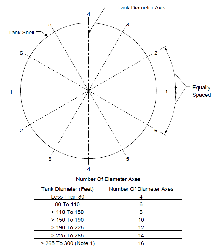
NOTE:
(*)For tank diameters greater than 300 feet, number of diameter axes shall be specified by the Owner's Engineer.
FIGURE 2
MEASUREMENT OF ELEVATION DIFFERENCE BETWEEN TANK AND SURROUNDING GRADE
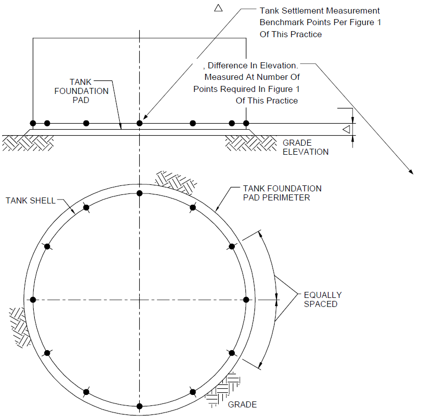
FIGURE 3
SPACING REQUIREMENTS FOR TANK BOTTOM ELEVATION MEASUREMENTS
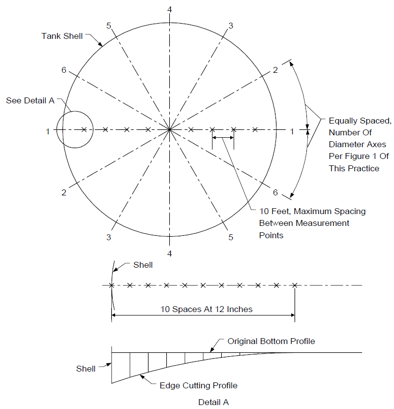
NOTE:
If edge cutting has occurred, measure elevation at one-foot increments along each axis.
FIGURE 4
TANK SHELL DIFFERENTIAL SETTLEMENT
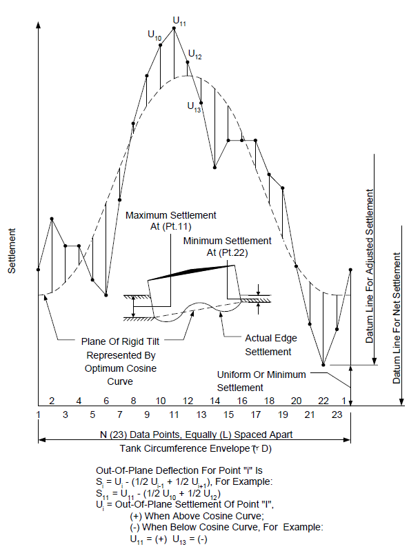
FIGURE 5
TIME - SETTLEMENT HISTORY
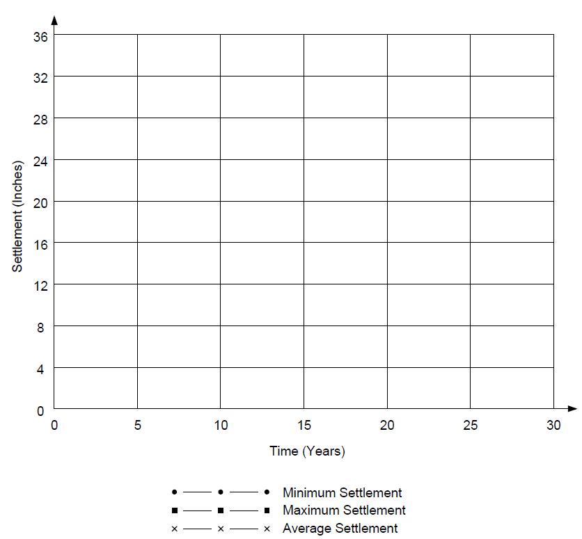
FIGURE 6
SETTLEMENT DATA POINT LOCATIONS
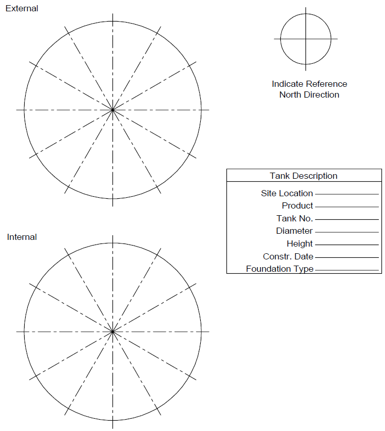
NOTES:
- Attach to tank foundation data sheet.
- Add diameter axes as required.
- Number axes and data points above.
FIGURE 7
EDGE CUTTING SETTLEMENT
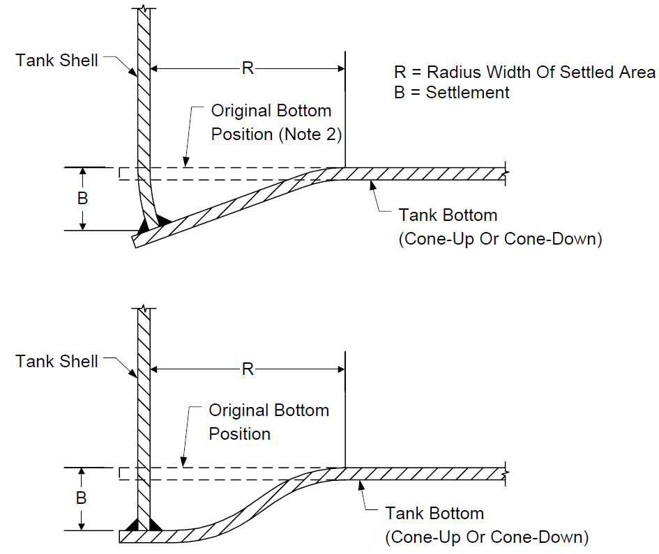
NOTES:
- See Figure 3 for measurement requirements for edge cutting settlement measurement.
- Original bottom position may not be flat.
FIGURE 8
TANK BOTTOM BULGES AND DEPRESSIONS
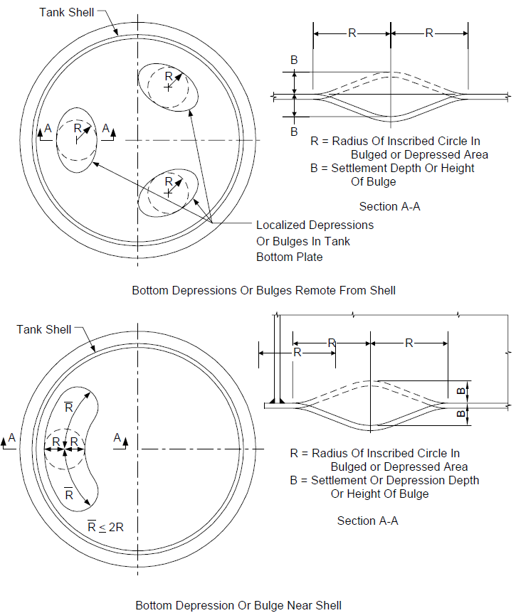
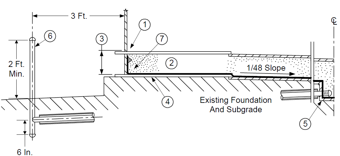
FIGURE 9
CONE-UP, EARTH PAD, DOUBLE BOTTOM

NOTE:
See Figure 10 for notes.
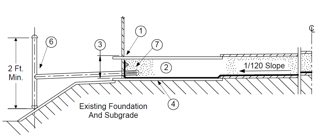
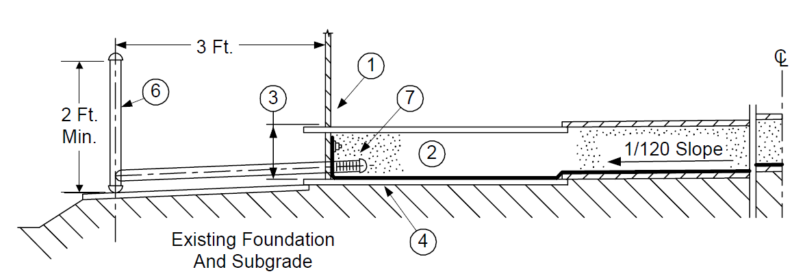
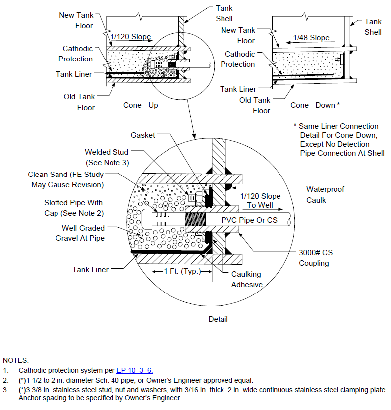
FIGURE 10
CONE-DOWN, EARTH PAD, DOUBLE BOTTOM
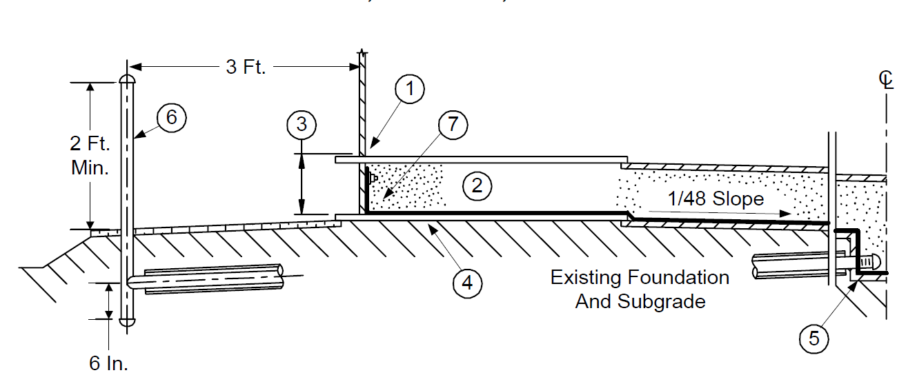
NOTES:
- See EP 9-1-5 for slot and floor details.
- See Table 1 for fill material.
- See Table 1 for slot height.
- (*)Impermeable membrane thickness and type to be specified by Owner's Engineer.
- See Figure 17 for center sump detail.
- (*)2 in. diameter, Sch. 40 CS tell-tape pipe, capped both ends (top cap removable) teed into 1 1/2 in. to 2 in. diameter, Sch. 40 CS pipe per Figure 21 of EP 4-2-7, or approved equal. 4 in. Sch. 40 coated carbon steel sleeve on buried horizontal run if specified by the Owner's Engineer. Alternate designs for monitoring wells, including but not limited to, sectional precast manholes or catch basins, shall be approved by the Owner's Engineer.
- See Figure 18 for detail.
- (Not shown) Cone-down tanks shall require a minimum of four equal-spaced perimeter pipes for drainage. This pipe shall be designed per Figure 18 (cone-up).
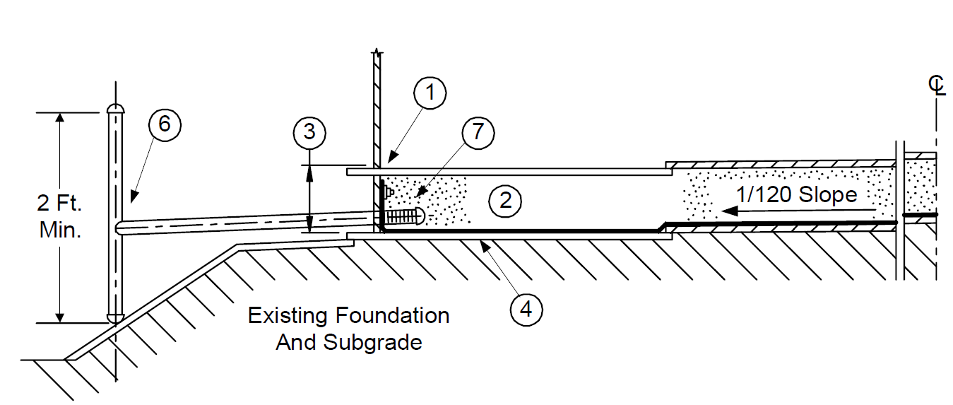
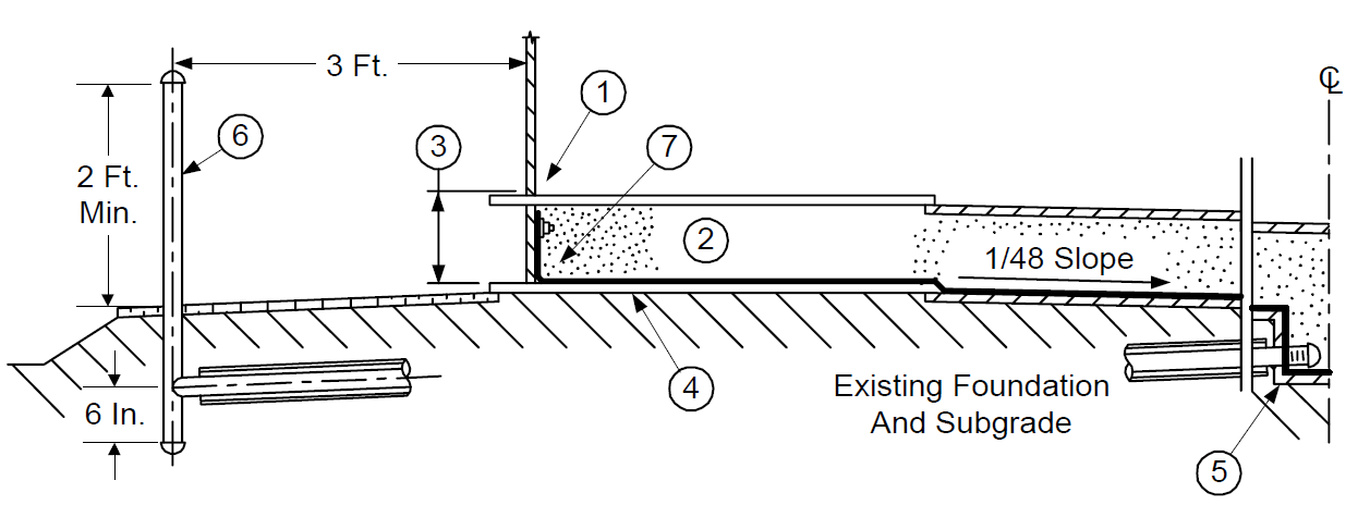
FIGURE 11
CONE-UP, GRAVEL RINGWALL DOUBLE BOTTOM
Note:
- See Figure 10 for Notes.
- May be revised after FE Parametric Study
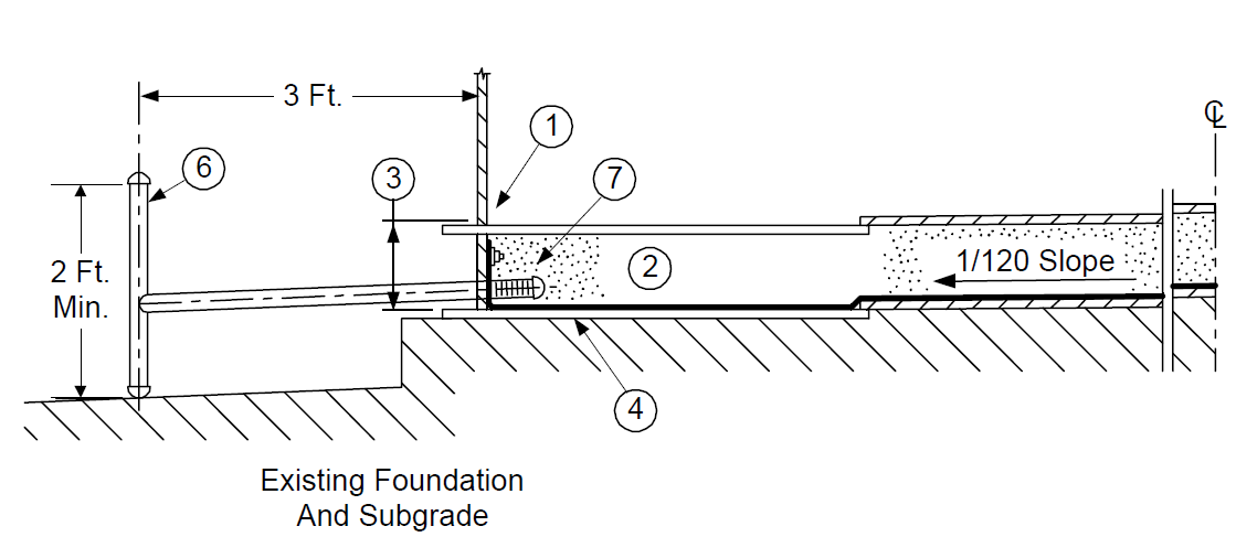
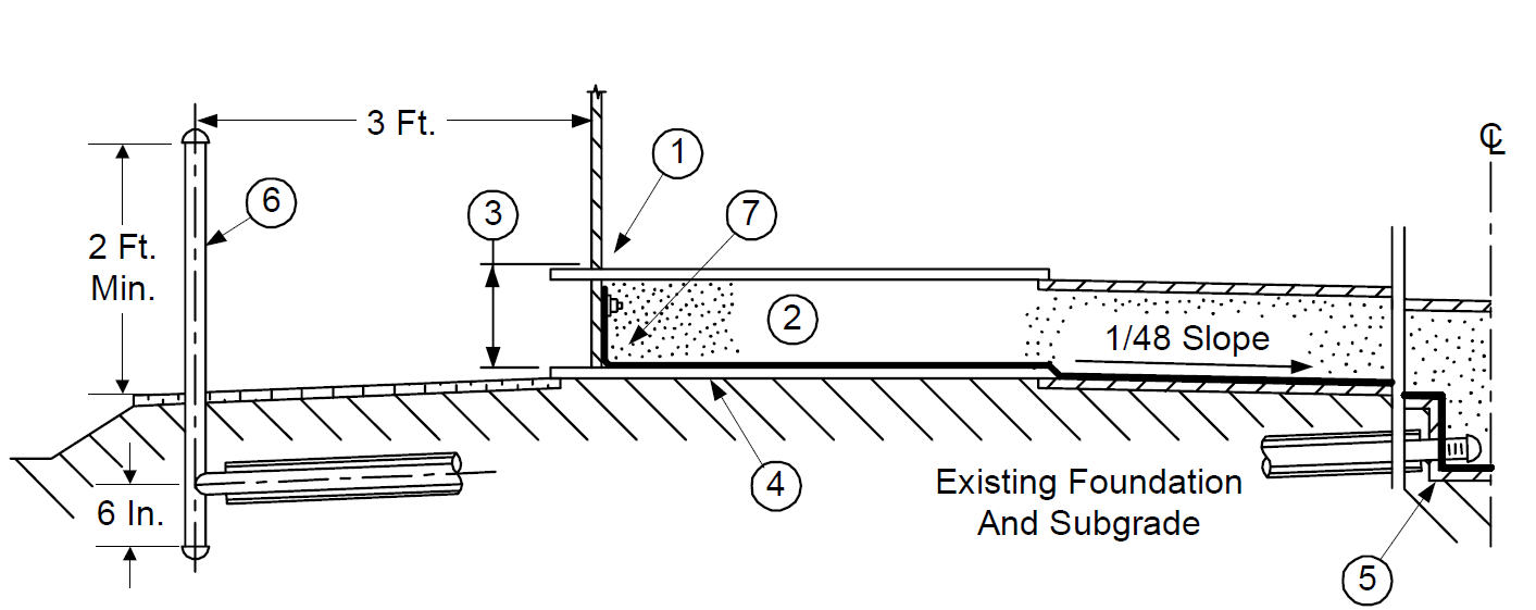
FIGURE 12
CONE-DOWN, GRAVEL RINGWALL DOUBLE BOTTOM*
Notes:
See Figure 10 for Notes.
May be revised after FE Parametric Study.
FIGURE 13
CONE-UP, CONCRETE RINGWALL DOUBLE BOTTOM
Notes:
See Figure 10 for Notes.
May be revised after FE Parametric Study.
FIGURE 14
CONE-DOWN CONCRETE RINGWALL DOUBLE BOTTOM
Notes:
See Figure 10 for Notes.
May be revised after FE Parametric Study.
FIGURE 15
CONE-UP, PILES/MAT, DOUBLE BOTTOM
Notes:
See Figure 10 for Notes.
May be revised after FE Parametric Study.
FIGURE 16
CONE-DOWN, PILES/MAT, DOUBLE BOTTOM
Notes:
See Figure 10 for Notes.
May be revised after FE Parametric Study.
FIGURE 17 CENTER SUMP DETAIL
NOTES:
- 1 1/2 to 2 in, Sch 40 PVC pipe inside 4 in, Sch. 40 CS sleeve per Figure 21 of EP 4-2-7.
- 1/4 in. thick CS plate, welded.
- Washed pea gravel.
- Geotextile filter, if required to hold sand.
- Cathodic protection system, details per EP 10-3-6.
- Hardware for PVC pipe per Figure 18.
- For tanks with center columns, center sump shall be offset.
FIGURE 18
DOUBLE BOTTOM LINER ATTACHMENT
© 2026 Inflection Point Engineering, LLC. All rights reserved. The content of this page — including calculation methods, reference data, written analysis, interactive tools, and source code — is the intellectual property of Inflection Point Engineering, LLC and is protected under applicable copyright, trademark, and trade secret laws. Unauthorized reproduction, redistribution, modification, or derivative use in whole or in part is prohibited without prior written consent.
Disclaimer. This material is provided for informational and educational purposes only and does not constitute professional engineering advice. Calculations, reference data, and methodologies are based on published standards and accepted engineering practice but are not a substitute for engineering judgment, site-specific analysis, or review by a licensed Professional Engineer. Inflection Point Engineering, LLC makes no warranties, express or implied, regarding the accuracy, completeness, or fitness for a particular purpose of any content presented here, and shall not be liable for any direct, indirect, incidental, or consequential damages arising from its use. Users assume all risk associated with applying this content to real-world design, operations, or decisions.
© 2026 Inflection Point Engineering, LLC. All rights reserved.