 Section 4 — Structures and Foundations
Chain Link Fence and Gates
IPE Engineering Practice IPE-EP-4-10-1
Document number: IPE-EP-4-10-1 · Section: 4 — Structures and Foundations
SCOPE
- This Practice covers mandatory requirements governing the design, selection of materials, and installation for temporary and permanent chain link fencing.
- This Practice is appropriate for attachment to inquiry or purchase documents.
- Deviations to this Practice must be approved by procedures described in EP 1-1-3.
- An asterisk (*) indicates that a decision or approval by the Owner or the Owner's Engineer is required, or that additional information is furnished by the Purchaser.
- A revision bar indicates all changes made to this Revision.
- Documentation required for the construction of chain link fences in accordance with this Practice is given in Table 4.
2.0 REFERENCES
The latest edition of the following standards and publications are referred to herein.
STANDARDS AND PUBLICATIONS
| IPE Engineering Practices |
|---|
| EP 1-1-3 Deviations to IPE Engineering Practices EP 4-1-1 Design Criteria and Loads for Structures EP 4-10-1C Chain Link Fence and Gates Inspection Checklist |
| ACI |
| 318 Building Code Requirements for Reinforced Concrete |
| ASTM Standards |
| A120 Pipe, Steel, Black and Hot Dipped Zinc-Coated Welded and Seamless for Ordinary Uses A121 Zinc-Coated (Galvanized) Steel Barbed Wire A123 Zinc (Hot-Galvanized) Coatings on Products Fabricated from Rolled, Pressed, and Forged Steel Shapes, Plates, Bars, and Strip A153 Zinc-Coating (Hot-Dip) on Iron and Steel Hardware A392 Zinc-Coated Steel Chain-Link Fence Fabric A491 Aluminum-Coated Steel Chain-Link Fence Fabric A585 Aluminum-Coated Steel Barbed Wire A641 Galvanized Carbon Steel Wire |
STANDARDS AND PUBLICATIONS (CONT.)
DEFINITIONS
- Contractor - Company or business that agrees to furnish materials or perform specified services at a specified price and/or rate to the Owner.
- Inspector - A Inflection Point Engineering, LLC appointed engineer or inspector.
- Manufacturer - The recipient of a direct or indirect purchase order for materials and/or equipment. In this context, a direct order is one issued to a manufacturer by a contractor or the Owner. An indirect order is one issued to a manufacturer by a vendor (recipient of a direct order) for materials, fabricated components, or subassemblies.
- Owner - Inflection Point Engineering, LLC.
- Owner's Engineer - A Inflection Point Engineering, LLC appointed engineer.
- Purchaser - The party placing a direct purchase order. The purchaser is the Owner's designated representative.
MATERIALS
- Acceptable materials of construction (steel) shall be per applicable standards listed in Paragraph 2.0 and Table 1.
- (*)Unless otherwise specified, concrete shall be made with ASTM C150 Type 1 cement. Aggregate shall comply with ASTM C33.
- All metal components of permanent fence (except barbed wire) are to be hot dip galvanized with a minimum zinc coating of 2.0 ounces per square foot of surface. Barbed wire shall have a minimum zinc coating of 0.80 ounces per square foot.
- Galvanizing shall be done by hot dip galvanizing processes as specified in Table 2.
- All material used for permanent fencing shall be new. No used, re-rolled, or open seam material will be acceptable.
DESIGN
(*)All applicable local, city or regional building codes specified in EP 4-1-1 shall be adhered to by the Contractor. Any conflicts between the requirements of such codes and this Practice shall be brought to the attention of the Owner for clarification or resolution. Design drawings and specifications shall be submitted to the Owner's Engineer.
- Fence
- Length of posts shall be as follows:
- Line and bracing post length shall equal fabric height plus 32 inches.
- Corner post lengths shall equal fabric height plus 36 inches.
- Gate and end post lengths shall equal fabric height plus 48 inches.
- See Table 1 for additional requirements.
- Corner, end and pull posts shall be steel pipe, conforming to the specifications of ASTM A120, 2-1/2 inch nominal diameter, and shall weigh not less than 5.79 pounds per linear foot. These posts shall be equipped with a moisture-proof extension arm. Pull posts are required for each 500 feet length of straight fence and where a change of 15 degrees or more in either grade or direction occurs.
- Line posts shall be steel pipe, conforming to the specifications of ASTM A120, 2-inch nominal diameter, and shall weigh not less than 3.65 pounds per linear foot. These posts shall be equipped with moisture-proof extension arm. Line posts shall be spaced not further apart than 10 feet on center.
- Pressed steel or malleable iron moisture-proof caps shall be provided on pipe posts that are not fitted with extension arms.
- Each end and each gate post shall be equipped with one brace assembly. Each corner and each bracing post shall be equipped with a brace assembly on either side of the post. Each brace assembly shall consist of one top and one intermediate compression member extending from the terminal or bracing post to the first adjacent line post. The lower panel shall be trussed from the line post back to the bottom of the terminal or bracing post with 3/8-inch round rod.
- (*)Top rails shall not be provided unless specified by Owner.
- (*)The centerline of the fence posts shall be one foot inside property line unless otherwise specified by Owner.
- See Figures 1 through Figure 4 for typical fence details.
- Tension Wire
- Tension wire shall be furnished at the top and bottom of the fabric.
- Bottom tension wire shall be 6-gage coil spring steel wire and shall be in accordance with the requirements of ASTM A641 Class 3. The tension wire shall be stretched on the posts before fabric is installed and tied securely to the posts 3 inches above finished grade.
- See Table 1 for further wire requirements.
- Tie Wire and Fabric Bands
- Tie wires shall be spaced at 2-foot intervals along the tension wires.
- Fabric bands or tie wires shall be spaced at 14-inch intervals on each post.
- See Table 1 for further requirements.
- Gates
- Gate frames shall be fabricated from steel pipe complying with ASTM A120 and shall be provided with diagonal cross bracing consisting of 3/8-inch diameter adjustable length truss rods. All gates shall be equipped with attachments for a padlock, accessible from both sides of the gate. Gate shall have the following hardware and accessories, as appropriate:
- Hinges: Pressed steel or malleable iron to suit gate size, non lift-off type, offset to permit 180-degree gate opening. One pair of hinges shall be provided for each leaf.
- Latch: Forked type or plunger-bar type to permit operation from either side of gate. A padlock eye shall be provided as an integral part of the latch.
- Keeper: Keeper for all vehicle gates, which automatically engages the gate leaf and holds it in the open position until manually released.
- Double Gates: Gate stops for all double gates, consisting of mushroom type or flush plate with anchors. Set in concrete to engage the center drop rod or plunger bar. Locking devices and padlock eyes shall be provided as an integral part of the latch, requiring one padlock for locking both gate leaves.
- Sliding Gates: Manufacturer's standard heavy-duty track, ball bearing hanger sheaves, overhead framing and supports, guides, stays, bracing, and accessories.
- Barbed Wire
(*)Unless otherwise specified by Owner, three strands of barbed wire shall be provided on top of the fabric potion of the fence, as follows:
- Extension arms, directed away from the area to be protected, shall be installed on top of each line and corner post to support the barbed wire. The arms shall be at a 45-degree angle with the plane of the fence.
- Each arm shall have equally spaced slots to hold the strands by means of lugs or stitch wire at a maximum of 6 inches center-to-center spacing.
- The topmost barbed wire shall be 12 inches above the fabric and 12 inches from the fence line.
- See Table 1 for further requirements.
- Top Rail
Top rails shall be steel pipe, conforming to ASTM A120 1-1/4 inch nominal diameter, and weigh not less than 2.27 pounds per linear foot. Top rails shall be provided with pressed steel couplings approximately every 20 feet. Couplings shall be outside sleeve type and shall be at least 7 inches long. One coupling in every 5 shall have a heavy spring to compensate for expansion and contraction of the top rail. Top rails shall pass through line post tops and shall form a continuous brace from end to end of each segment of fence. Top rails shall be securely fastened to end, corner, pull and gate posts by pressed steel connections.
- Stretcher Bars
Stretcher bars shall be mild steel bars, one piece, with a length equal to the full height of fabric and a minimum cross section of 3/16-inch x ¾-inch. One stretcher bar shall be threaded through the fabric for each gate and end post, and two for each corner and pull post.
- Braces
- Braces shall be the same material as the top rail. Braces shall be spaced midway between the top rail and the ground and extend from end, pull, corner and gate posts to the first adjacent line post. Braces shall be securely fastened to posts by suitable pressed steel connections, then trussed from line posts back to the base of end, pull, corner or gate posts with 3/8 inch round rods fitted with a turnbuckle. Post braces shall be provided at each end and gate post. In addition, pull and corner posts shall be braced in both directions.
- See Table 1 for further requirements.
- Extension Arms
Extension arms and fittings shall be malleable iron or pressed steel. Extension arms shall be integral with a weather tight closure cap for tubular posts and shall carry 3 barbed wires at an angle of 45 degrees, facing the outside of the property. Topmost wire of extension arms which are inclined at 45 degrees shall be approximately 12 inches horizontally away from the fence line and the other wires shall be equally spaced between the top of the fence fabric and the top barbed wire. Barbed wires shall be securely fastened to extension arms. Arms shall be capable of withstanding a 300-pound downward pull at the end of the extension arm.
- Concrete
- Concrete for fence posts shall be designed, mixed and placed in accordance with ACI 318.
- Ready-mixed concrete shall conform to ASTM C94 with minimum compressive strength of 3000 pounds per square inch at 28 days.
- Maximum aggregate size shall be 1-1/2 inches.
- Concrete slump shall be 2 to 4 inches as measured in accordance with ASTM C143.
CONSTRUCTION
- Excavations shall be "neat cut" in clays and other cohesive soils with the concrete deposited against the sides of the excavations. Forms shall be used in granular soils where "neat cut" is not possible.
- (*)All excess material from footings shall be disposed of by the Contractor as directed by the Owner's Engineer.
- Backfilling, where required, shall be with an approved material compacted to 90% of the maximum dry density obtained by the Modified Proctor Density Test per ASTM D1557.
- Footings shall be cylindrical in shape with the top of concrete being 2 inches above finished grade, as measured at the post, unless obstructing traffic through gates. The concrete shall slope away from the post with at least a ½-inch drop from the center to the edge of the footing.
- The minimum footing dimensions are given in Table 3. The depth shall be measured from finished grade to the bottom of concrete. The bottom of concrete shall be at least 4 inches below the bottom of the post.
- All water and debris shall be removed from the excavation prior to pouring concrete.
- Posts shall be adequately secured against misalignment during pouring of concrete and for 24 hours thereafter.
- Concrete shall be rodded or otherwise densified around the posts.
- The fabric bottom shall follow existing finished grade contours with not more than 2 inches clearance below the bottom of the fence.
- After fence erection, the Contractor shall be responsible for any additional grading required to eliminate excessive gaps or openings between the bottom of the fabric and the finished grade. In ungraded areas, the fence shall follow the existing ground line. Minor irregularities shall be removed or filled in by grading for a distance of 2 feet on each side of the fence.
- Posts shall be installed plumb and true and checked for alignment. Bracing shall be installed so posts are plumb when diagonal rods are under proper tension.
- Fabric shall be pulled taut to eliminate all slack edges and warped sections and tied to posts, rails, braces and tension wires. Fabric shall be installed so that the posts are enclosed and anchored to framework such that fabric remains in tension after pulling forces are released.
- The outside face of the fabric shall be considered the fence line. This line shall follow the specified line within a tolerance of 1/2 inch.
- Gates shall be installed plumb, level and secure, and provide full opening without interference. Hardware shall be adjusted for smooth operation.
- The final fence installation shall be inspected and compliance with the drawings and specifications verified. Results of this inspection shall be recorded on EP 4-10-1C.
7.0 TEMPORARY (CONSTRUCTION) FENCING
- (*)Temporary fencing shall be installed per drawings or as directed by the Owner.
- (*)Unless otherwise specified by the Owner, temporary fencing shall not require barbed wire security material, and may be of lesser quality than required for permanent fencing.
- (*)The Contractor shall provide the material specification for a lesser quality fabric and gates for temporary fencing, for approval by the Owner. Temporary fencing will generally have 'lighter' construction materials with regards to fabric, line post, and gate post diameter.
8.0 TABLES
TABLE 1 MATERIALS OFCONSTRUCTION
| COMPONENT | FOR GALVANIZED STEEL FABRIC |
FOR ALUMINUM COATED STEEL FABRIC |
|---|---|---|
| FABRIC Material |
ASTM A392 Class 2 | ASTM A491 |
| Min Tensile Strength | 85,000 psi | 80,000 psi |
| Weave | Per ASTM A392 2 in. mesh, barbed top and bottom |
Per ASTM A491 2 in. mesh, barbed top and bottom |
| Wire Diameter | 0.148 in. | 0.148 in. |
| Width | 7ft. (1) | 7ft. (1) |
| BARBED WIRE Material |
ASTM A121 Class 3 | ASTM A585 Barb - Al Alloy Wire - Al coated (0.3 oz/ft2 ) steel |
| Barb Spacing | No Greater Than 4 in. | No Greater Than 4 in. |
| Wire Diameter | 0.105 in. | 0.105 in. |
| Barb Diameter | 0.080 in. | 0.098 in. |
| CONNECTORS Materials |
||
| - Tie Wires | A1 Alloy | Al Alloy |
| - Other Conn. | Galvanized Steel | Galvanized Steel |
| TENSION WIRE Material |
Galvanized Steel: Electrolytically coated - 1.8 oz/ft2 |
Al coated (.4 oz/ft2) steel |
| Wire Diameter | 0.177 in. | 0.177 in. |
TABLE 1
MATERIALS OF CONSTRUCTION (CONT.)
| COMPONENT | COMPONENT | MATERIAL (BOTH FABRIC TYPES) |
|---|---|---|
| POSTS AND FRAMES Material |
POSTS AND FRAMES Material |
Galvanized steel hot dipped per ASTM A123 |
| Min. Tensile Strength | 45,000 psi | |
| Sizes - Line Posts |
||
| Sizes - Line Posts |
1.875 inches x 1.625 inches Roll-Formed Section, 2.34 lb/ft (USS) or 2 inches SCH 40 pipe |
|
| - Terminal Posts | - Terminal Posts | 3-1/2 inches x 3-1/2 inches Roll-Formed Section, 5.16 lb/ft (USS) or 2-1/2 inches SCH 40 pipe |
| - Bracing and Top Rail | - Bracing and Top Rail | 1.625 inches x 1.25 inches Roll-Formed Section, 1.35 lb/ft (USS) or 1-1/4 inch SCH 40 pipe |
| - Gate Frames | - Gate Frames | 1-1/2 inch SCH 40 pipe |
| - Gate Posts for Width 6 ft. or less |
- Gate Posts for Width 6 ft. or less |
2-1/2 inch SCH 40 pipe |
| 6 to 12 ft | 6 to 12 ft | 3-1/2 inch SCH 40 pipe |
| 12 to 18ft | 12 to 18ft | 6 inch SCH 40 pipe |
| 18 to 22 ft. | 18 to 22 ft. | 8 inch SCH 40 pipe |
| MATERIALS FOR OTHER COMPONENTS | MATERIALS FOR OTHER COMPONENTS | Galvanized steel hot dipped per ASTM A123 |
NOTE:
(1) (*)Unless otherwise specified.
TABLE 2 GALVANIZING
| Steel Shapes, Plates, Bars, Strips Steel Pipe Fabric (after weaving) Fittings and Hardware Barbed Wire Tension Wire |
ASTM A 123 ASTM A120 ASTM A392 Class 2 ASTM A153 ASTM A121 CIass3 ASTM A641 Class 3 |
|---|
TABLE 3
MINIMUM FOOTING DIMENSION
| POST DESCRIPTION | DEPTH INCHES |
DIAMETER INCHES |
|---|---|---|
| Line Post | 36 | 10 |
| Corner Posts | 42 | 16 |
| End Posts | 42 | 16 |
| Pull Posts | 42 | 16 |
| Gate Posts for Gates up to 12 Feet Wide | 42 | 16 |
| Gate Posts for Gates Over 12 Feet to Gates 18 Feet Wide | 60 | 20 |
| Gate Posts for Gates Over 18 Feet to Gates 22 Feet Wide | 72 | 26 |
TABLE 4 DOCUMENTATION REQUIREMENTS FOR CHAIN LINK FENCE AND GATES PER EP 4-10-1
| Item | Description | Format | As-Built |
|---|---|---|---|
| 1 | Drawings and specifications | See EP 2-5-2 | Yes |
| 2 | Results of field inspections | See EP 2-5-2 | N/A |
9.0 FIGURES
FIGURE 1 CHAIN LINK FENCING
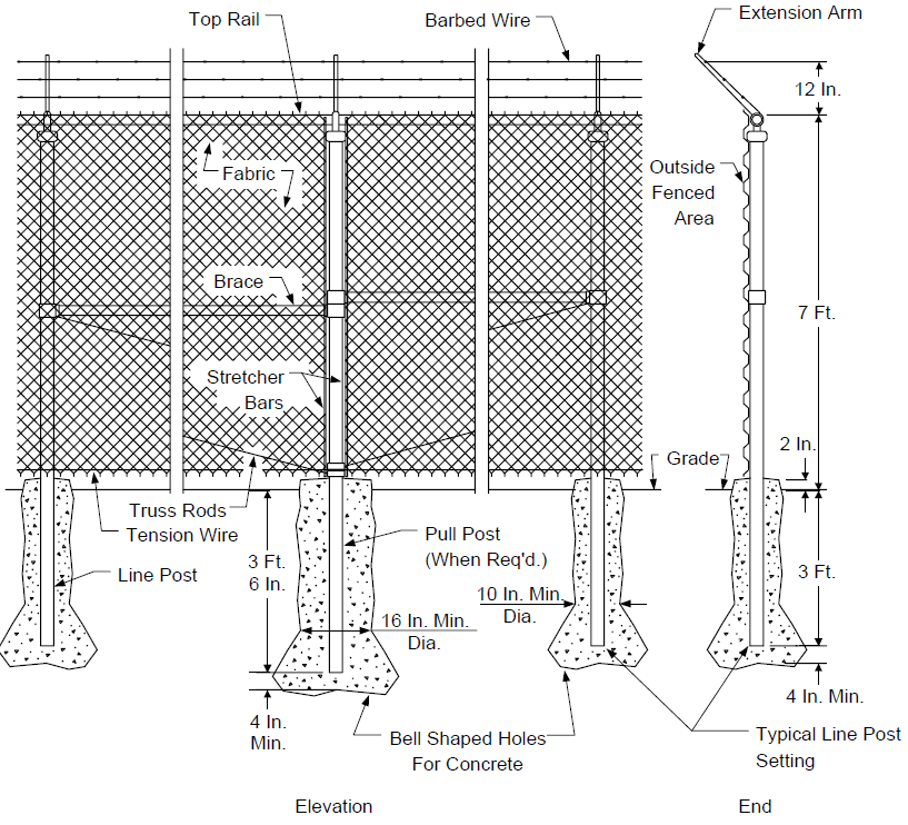
FIGURE 2
CORNER OR END POST FOR CHAIN LINK FENCING
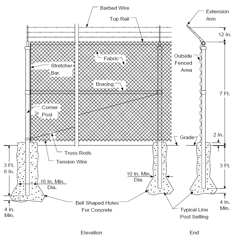
FIGURE 3
PERSONNEL GATE FOR CHAIN LINK FENCING
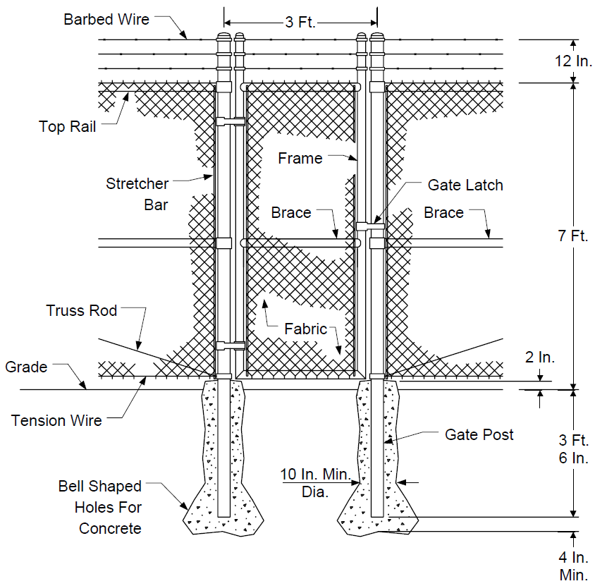
FIGURE 4
DOUBLE DRIVE GATE FOR CHAIN LINK FENCE
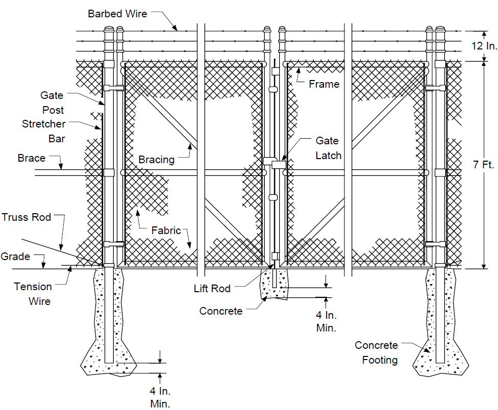
NOTE: Footings shall be flush with grade to only slightly raised, 1/2 in. maximum, at vehicle traffic gate locations.
© 2026 Inflection Point Engineering, LLC. All rights reserved. The content of this page — including calculation methods, reference data, written analysis, interactive tools, and source code — is the intellectual property of Inflection Point Engineering, LLC and is protected under applicable copyright, trademark, and trade secret laws. Unauthorized reproduction, redistribution, modification, or derivative use in whole or in part is prohibited without prior written consent.
Disclaimer. This material is provided for informational and educational purposes only and does not constitute professional engineering advice. Calculations, reference data, and methodologies are based on published standards and accepted engineering practice but are not a substitute for engineering judgment, site-specific analysis, or review by a licensed Professional Engineer. Inflection Point Engineering, LLC makes no warranties, express or implied, regarding the accuracy, completeness, or fitness for a particular purpose of any content presented here, and shall not be liable for any direct, indirect, incidental, or consequential damages arising from its use. Users assume all risk associated with applying this content to real-world design, operations, or decisions.
© 2026 Inflection Point Engineering, LLC. All rights reserved.