 Section 3 — Process Safety & Loss Prevention
Firewater Systems
IPE Engineering Practice IPE-EP-3-5-2
Document number: IPE-EP-3-5-2 · Section: 3 — Process Safety & Loss Prevention
1.0 SCOPE 5
2.0 REFERENCES 5
3.0 DEFINITIONS 6
4.0 APPLICABILITY 7
4.1 Good Engineering Practice 7
4.2 Available Personnel 7
4.3 Federal and Local Requirements 7
4.4 Required Fire Fighting Facilities 7
4.5 Pre–Fire Plans 8
4.6 Summary of Provisions 8
5.0 FIREWATER SYSTEM SERVICE CONDITIONS 8
5.1 Design Basis 8
5.2 Largest Combined Firewater Demand 9
5.3 Process Unit Firewater Demand 9
5.4 Atmospheric Storage Tank Firewater Demand 9
5.5 Firewater Demand for Pressurized Storage 10
5.6 Auxiliary Requirements 10
5.7 Firewater Supply 10
5.8 Firewater Contamination 11
6.0 REQUIREMENTS FOR FIRE MAIN PRESSURES 11
6.1 Residual Pressure 11
6.2 Residual Pressure Considerations 11
7.0 FIRE PUMP DESIGN REQUIREMENTS 12
7.1 Firewater Pumping Capacity 12
7.2 Pump Type and Arrangement 12
7.3 Pump Size 13
7.4 Types of Drivers 13
7.5 Firewater Pressure Maintenance 14
7.6 Fire Pump Starting 15
7.7 Pump Enclosure 15
9.0 FIRE MAIN AND HYDRANTS ARRANGEMENTS 15
9.1 Fire Main Design 15
8.2 Fire Main Size and Rating 16
8.3 Fire Hydrant Locations and Sizes 17
9.0 MONITORS 19
9.1 General 19
9.2 Limitations and Location Guidelines 19
9.3 Water Monitors 19
9.4 Installation Requirements 19
9.5 Portable Monitors 20
9.6 Application 20
10.0 TABLES 21
TABLE 2 FIREWATER MONITORS 21
TABLE 3 FOAM/WATER MONITORS 22TABLE 3 FOAM/WATER MONITORS 22 Table 4 Documentation Requirements 22Table 4 Documentation Requirements 22
11.0 FIGURES 23
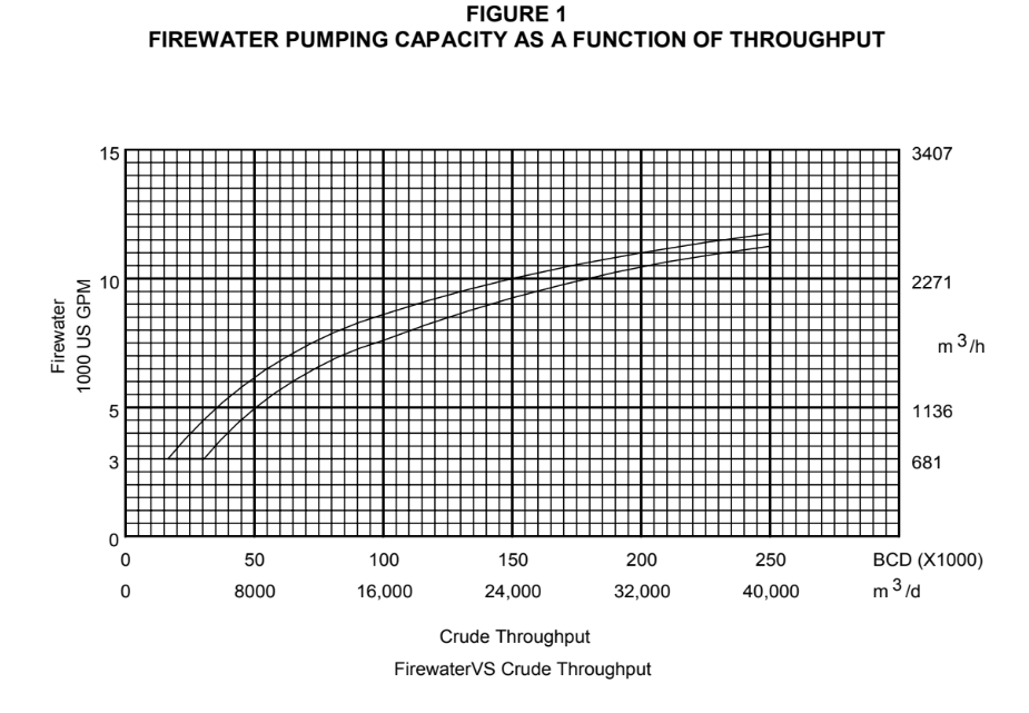
Figure 1 Firewater Pumping Capacity as a Function of Throughput 23
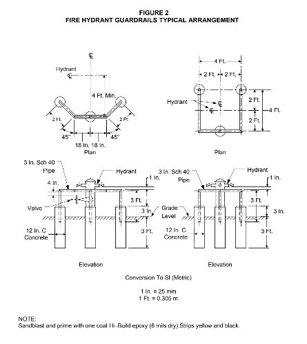
Figure 2 Fire Hydrant Guardrails Typical Arrangement 24
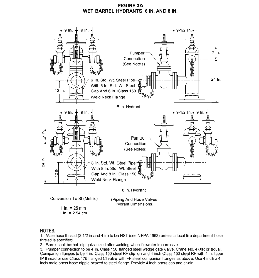
Figure 3A Wet Barrel Hydrants 6 In. and 8 In. 25
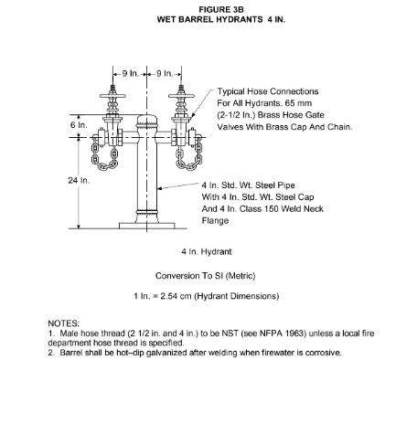
Figure 3B Wet Barrel Hydrants 4 In. 26
Figure 4 Typical Siting of Monitors 27
Figure 5 Monitor Guardrails Typical Arrangement 28
Figure 7 Typical Firewater System 30
SCOPE
- This Practice defines the design requirements for firewater systems including firewater source, capacity, distribution piping, hydrants, and firewater monitors. This Practice provides overall definitions of loss prevention requirements as well as providing references to other engineering standards and practices for design details.
- The Practice applies to all IPE plants. Procedures and data are included to enable the designer to insure that a safe, operable facility is built with adequate, but not excessive, fire fighting equipment.
- Any deviation from this Practice must be approved by the procedure described in EP 1–1–3.
- A revision bar indicates all changes made to this Revision.
- Documentation required for firewater systems constructed in accordance with this Practice is given in Table 4.
2.0 REFERENCES
The latest edition of the following standards and publications are referred to herein.
STANDARDS AND PUBLICATIONS
| IPE Engineering Practices |
|---|
| EP 1–1–3 Deviations to IPE Engineering Practices EP 6–3–1 General Purpose Steam Turbines EP 6–3–2 Special Purpose Steam Turbines EP 10–3–3 Corrosion Protection for Underground Pipe |
| API Recommended Practices |
| RP 2001 Fire Protection in Plants |
| NFPA Codes |
| No. 11 Low Expansion Foam and Combined Agent Systems No. 13 Installation of Sprinkler Systems No. 15 Water Spray Fixed Systems No. 20 Installation of Centrifugal Fire Pumps No. 24 Installation of Private Fire Service Mains No. 30 Flammable and Combustible Liquids Code No. 321 Basic Classification of Flammable and Combustible Liquids No. 1901 Pumper Fire Apparatus No. 1963 Fire Hose Thread Connections |
DEFINITIONS
- Aqueous Film Forming Foam (AFFF) - A foam that develops an aqueous film on a fuel surface that suppresses the evolution of fuel vapor. AFFF is most effective for control of hydrocarbon spill fires and is compatible with dry chemical extinguishing agents. (see NFPA 11 for detailed description and system requirements.)
- Authority Having Jurisdiction - The organization, office, or individual responsible for approving equipment, installations, and procedures.
- Automatic Application - The process by which the fire extinguishing agent is applied as a result of an initiating impulse from a fire or gas detector.
- Boilover - The expulsion of crude oil from a burning tank, caused by a heat wave reaching a water stratum. The light fractions of the crude distill, burn off, and produce the heat wave in the residue.
- Class A Fires - Fires involving ordinary combustibles, such as wood, paper, textiles, and trash.
- Class B Fires - Fires involving flammable liquids, greases, etc.
- Class C Fires - Fires involving live electrical equipment where electrical non-conductivity of the extinguishing agent is of first importance.
- Class I Liquids - Liquids having flash points below 100°F. See NFPA 321 for classification of subdivisions of Class I, II, and III liquids.
- Concentrate - A concentrated liquid foaming agent (foam or AFFF), as received from the manufacturer. It is diluted with water to form a 1% to 6 % solution, depending on the type of concentrate.
- Dry Pipe Fire Main System - A fire main system that can be shut off and drained when not in use for service in freezing climates.
- Foam - A stable aggregation of small bubbles of lower density than oil or water that flows freely over a burning liquid surface and forms a tough continuous blanket to seal volatile combustible vapors from access to air. Foam is produced by mixing air into a solution of water and foam concentrate.
- Jockey Pump - A small pump, usually motor driven, and designed for a flow rate of about 100 gpm, used to maintain design pressure in the fire main system. When the flow rate exceeds rated capacity, the main fire pumps are started automatically.
- Live Hose Reel - A reel equipped with swivel pipe inlet and non-collapsible hose, so that only the amount of hose needed is pulled from the reel before use.
- Monitor - A turret supporting a nozzle with water or foam capacity sufficient for fire fighting yet operable by one person and arranged so that it can be locked in position for a fixed discharge of water or foam.
- Owner - Inflection Point Engineering, LLC.
- Owner’s Engineer - A Inflection Point Engineering, LLC appointed engineer.
- Residual Pressure - The firewater pressure at a defined location, which is established by the pressure drop from a source at design flow.
APPLICABILITY
The requirements contained in this specification are minimum design requirements based on National Fire Protection Association (NFPA) codes, American Petroleum Institute (API) standards and good engineering practices. Key assumptions that form the basis for these standards are as follows:
- Good Engineering Practice
Specification requirements are based on the assumption that process and equipment design follow good engineering practice, as defined by the IPE Engineering Practices and accepted industry practices. Where design or equipment is less than defined by good practice standards, firefighting facilities may need expansion after a fire protection engineering analysis of the risk involved. For example, this will occur when equipment spacing is less than adequate or when a control room is not blast resistant.
- Available Personnel
During an emergency, personnel are usually preoccupied with safe, timely equipment shutdown and minimal manpower is available to fight fires. The requirements of this specification are based on a minimum of plant operators being available for firefighting.
- Federal and Local Requirements
Recognized Federal and/or local codes and standards shall be followed unless the requirements of this specification are more stringent. If Federal and local requirements are more stringent, the requirements of this specification shall be followed with the written approval of the authority having jurisdiction.
- Required Fire Fighting Facilities
- (*)A hazard analysis shall be conducted to determine the extent of the required fire fighting facilities. Fire prevention and fire fighting facilities to prevent injury or loss of life shall be adequate for the conditions of the facility. Prevention of the spread of a fire to adjoining property shall also be a primary consideration. The Owner’s Engineer shall approve the results of the analysis prior to the final fire control systems design.
- The review of hazards and plant arrangements shall include examination of the following:
- Process unit plot plans and overall plant layout.
- Process information, including characteristics of materials handled, and design operating conditions including pressures and temperatures.
- Relief system design.
- Vapor depressurizing, where provided.
- Materials of construction, including vessel insulation, fireproofing systems and use of cast iron or non–ferrous materials in hydrocarbon service.
- Pre–Fire Plans
- Pre–fire plans must be prepared to determine the adequacy of the firewater system. Such plans should recognize that some fires cannot be extinguished, e.g. fully involved fires in tanks greater than 150 feet in diameter may inevitably lead to escalation and involve more than one tank. Primary consideration has to be given to the safety of the general public, firefighters and site personnel and should be a part of the pre–fire plan and emergency procedure. Factors that shall be considered in pre–fire plans are:
- Fire fighting philosophy and methodology to be adopted (dependent upon immediate manpower availability, location of site, mutual aid requirements, etc).
- Fixed, semi–fixed and portable monitors required or available.
- Fire truck location, hose lays and pumping pressure required to deliver rated flows to determine number, spacing and size of hydrants.
- Breakdown of water requirements for foaming, for protecting adjacent exposures and for hoselines.
- Summary of Provisions
- The following summary shall be used as a guide in determining required fire fighting facilities:
- Firewater: For plant firewater requirements, See Section 5.0 of this Practice.
- Fire Pumps: Determine fire pump requirements in accordance with Section 7.0 of this Practice.
- Fire Mains and Hydrants: Locate hydrants, including size and type, on individual process unit plot plans in accordance with Section 7.0 of this Practice. The fire main grid and offsite hydrants can then be located on the overall plant plot plan.
- Fixed Water Spray Systems: Review each unit plot plan to determine high–hazard areas and equipment subject to fire exposure.
- Monitors: Determine fixed or portable monitor requirements in accordance with Section 8.0 of this Practice.
FIREWATER SYSTEM SERVICE CONDITIONS
- Design Basis
- General: Determine minimum firewater distribution system capacity by calculation of the:
- Largest combined fire contingency,
- Process unit firewater demand,
- Tank farm firewater demand, and
- Pressure storage firewater demand.
- Calculation procedures described in Sections 5.2 through 5.6 shall be used. The firewater distribution system design capacity shall be that needed to control the largest single fire risk calculated for the four items above. The distribution system shall be designed to deliver calculated system capacities to the respective plant location(s) at the specified pressures.
- Minimum Firewater System Design Capacity: The firewater design capacity shall not be less than 5000 gpm at the required pressure, providing the following conditions are satisfied.
- When the plant investment is low, and the plant design presents no dangerous exposure to onsite personnel, the public, or outside property.
- When equipment spacing is sufficient so that one fire may be fought at a time while other fires burn, but do not spread.
- When sufficient protection facilities are incorporated in the design to prevent any possible spread of the original fire.
- Sea Water: If sea water is used in fire fighting, a fresh water storage facility and associated jockey pump is required. This will permit the initial fill of the fire mains to be fresh water to minimize corrosion. It will also permit the system and associated firefighting facilities to be flushed through with fresh water after the necessary periodic tests with sea water. Steel pipe shall be concrete lined to insure internal corrosion resistance and greatly lessen friction losses.
- Largest Combined Firewater Demand
- The largest single firewater demand shall be determined by Section 5.3 of this Practice, with the exception of existing plants with inadequate spacing. When minimum spacing requirements are not provided for separation of process units or for adjacent facilities (storage tanks, pressure storage spheres, loading racks, etc.), the sum of the firewater demand for the process unit and the adjacent facility will be used as the firewater demand for that area of the facility.
- The combined firewater demand for congested areas shall be at least the amount determined by Section 5.3 of this Practice. Where the increased firewater demand for a specific area exceeds the system design capacity determined by Section 5.3, the system will be designed to supply water at the higher rate in that area of the facility.
- Process Unit Firewater Demand
- Plant Process Units: Determine process unit firewater requirements by calculating the sum of the water–consuming, fixed or portable, firefighting devices that may be used to extinguish fires or cool structures and equipment until shutoff of a fuel source or until the unit can be depressurized and shut down. Assume that at least two–thirds of fixed fire fighting equipment, (including fixed fire monitors and water spray systems) plus two 250 gpm hose streams will be required during a major fire. This rate shall not be less than the minimum rate listed in Table 1 for a specific process unit’s firewater requirement.
- Petrochemical Process Units: Petrochemical process unit firewater requirements shall be determined in the same manner as described in 5.3.1. The minimum firewater rate shall be 5000 gpm. A rate of 9000 gpm shall be used for larger units or closely grouped units containing large volumes of volatile products under high pressures.
- Atmospheric Storage Tank Firewater Demand
The largest–diameter cone roof tank may determine the maximum firewater requirement for a given tank farm and may dictate the plant firewater design capacity. NFPA 11 shall be used to determine firewater requirements for all types of atmospheric storage tanks.
- Fixed Roof Tanks Containing High–Flash Liquids: When the stored product has a closed–cup flash point of 150°F or higher, a fixed roof tank is normally considered safe. Water or foam extinguishment is not required provided all of the following conditions are met:
- There is no possibility of the storage temperature exceeding either the flash point or 200°F, for heated products.
- There is no possibility of hot oil streams entering the tank at temperatures above 200°F or within 10°F of their flash point.
- Blending with cutter stock having a flash point below the storage temperature, in the storage tank is not permitted.
- Sufficient firewater is available to cool exposed adjacent tankage in the event of ignition. Tank spacing is in accordance with NFPA 30.
- The product is not crude oil with boilover characteristics that require extinguishment before the heat wave from a fire reaches water at the tank bottom.
- Storage temperatures between 200°F and 250°F have been avoided, to avoid potential of a serious frothover.
- Foam extinguishment is not required for products heated above 250°F since slopover will occur if foam is applied.
- Firewater Demand for Pressurized Storage
- (*)Pressure Storage: The water requirement for cooling larger diameter pressure storage spheres or closely spaced drums may exceed maximum cone roof tank firewater requirements. Refer to NFPA 15 and the Owner’s Engineer to determine the firewater requirements. When adjacent spheres are not over 50 feet in diameter and are at least 100 feet apart (shell to shell), cooling of the adjacent spheres may be disregarded, when reviewed and approved by Owner’s Engineer.
- Low–Pressure Refrigerated Storage: Water for monitor cooling streams shall be available to cool tank shells that are directly exposed to fire. Water must not be applied directly to refrigerated LP–gas or cryogenic flammable liquid spills or spill fires, to avoid development of rapid vapor evolution or increased fire intensity.
- Auxiliary Requirements
- Pier and Wharf Firewater Requirements: Sufficient firewater shall be provided to supply any fixed monitors and below–deck foam or water sprinklers in the vicinity of a loading or unloading area, plus four to six hose streams. The required rate will vary from 2000 to 5000 gpm, depending on the size of barges or tankers using the installation, the type of wharf (T–head or L–head), and the number of tankers or barges using the wharf simultaneously.
- Cooling Water for Exposed Tankage: During a tank or sphere fire, cooling streams may be needed for adjacent tankage. However, where process units have insufficient volume of flammable liquids needed to generate enough heat to require cooling adjacent tankage, adjacent cooling systems may not be needed. Cooling water requirements shall be determined in accordance with NFPA 11.
- Office and Administrative Areas: Sufficient firewater shall be provided to supply any water sprinkler systems and standpipe systems in addition to hose streams. Minimum water requirements for buildings protected by automatic sprinkler systems shall be in accordance with NFPA 13. Where automatic fixed fire protection systems are not provided, a minimum required rate of 3000 gpm shall provided for the hose streams supplied by structure fire fighting pumpers.
- Firewater Supply
A firewater source shall be provided from either an unlimited source, such as a natural body of water, a storage tank or reservoir. Storage tank or reservoir capacity shall be sized to provide a minimum of six hours continuous operation of the fire pumps at rated capacity. After the initial six hours of operation the water source must also be capable of supplying one half of the maximum pumping capacity for a minimum of twelve additional hours. This continuous supply is based upon shutting down all non-critical operations before the end of the six-hour time period.
- Firewater Contamination
Plant effluent shall not be used as a firewater source for fire fighting foams (protein, fluoroprotein, AFFF’S, alcohol types) when emulsion–breaking or anti–foaming compounds are used for water treatments. Firewater intakes shall be located so as to avoid contamination by plant effluent or sewage. Contaminated foam is not fire resistant and allows the foam blanket to break down when exposed to the heat of a fire.
REQUIREMENTS FOR FIRE MAIN PRESSURES
- Residual Pressure
- The minimum fire main residual pressure shall be 100 psig at the hydrant outlet farthest from the main fire pumps. The specified pressure will provide adequate pressure for monitors, systems, and use of 250 feet of 2–1/2 inch hose directly from hydrants. Fire main pressure shall not exceed 165 psig at any location in the plant. The upper limitation permits proper operation of foam producing equipment and provides safeguards for personnel handling hose lines.
- Exceptions:
- The residual outlet pressure at the hydrant connection farthest from the main fire pump in a storage tank area may be reduced to not less than 50 psig when fire streams are to be provided from plant fire trucks with adequately sized pumps.
- (*)Small plants with relatively small total plant area can be arranged with a pressurized fire main system in lieu of a foam truck or trailer with booster pump. These systems shall be arranged with minimum residual hydrant pressure at the farthest hydrant of no less than 150 psig. Owner’s approval is required for plants where foam trucks are not provided.
- Residual Pressure Considerations
Fire main residual pressure shall be sufficient to satisfy pressure requirements for cooling streams, fog nozzle streams, and foam hose streams using pickup tubes. There must be sufficient pressure to supply fixed water spray systems, fixed monitors, and firewater needs at the highest plant elevation. Additional booster pumps may be used where unusual elevation changes are present on the site.
- Pumper Connections: Residual pressure at the hydrant pumper connection shall meet foam fire truck design requirements. Balanced pressure foam proportioning equipment shall be limited to a maximum PCS change pressure of 165 psig.
- Nozzles Pressures: Nozzle pressures differ according to size and type of nozzle, such as, smooth bore, adjustable fog, or foam type. System operating pressures shall be adequate for both large–capacity and hand–line nozzles used on 250 feet of 2–1/2 inch hose line. Nozzle manufacturer’s specifications on reach, type, and size shall be consulted in the system design.
- Fixed Water Spray and Foam/Water Spray Systems: Sufficient pressure shall be provided at the spray head to produce the required water or foam coverage, and to form water or foam droplets of the proper size to meet design requirements. The residual pressure at the main fixed system strainer outlet shall be at least 90 to 100 psig but not more than 165 psig on balance pressure foam systems to assure proper operation of foam equipment.
- Elevated Structures: Static head and pipe friction drop of systems on high structures will reduce residual pressure to a point where firefighting devices may be ineffective. A booster pump with reliable driver shall be provided to meet fire protection requirements in a safe location at the base of each structure. Foam fire truck pumps can be used as an alternate to provide the required pressure on high structures. To use a fire truck as the primary source of firewater, a fire hydrant and standpipe connection to the firewater system shall be provided on the structure in a safe, convenient location at least 100 feet from the base of the structure.
- Plants Grade Differences: When the main fire pumps are located at a higher elevation, static head will aid in providing the required residual pressure and the pumps will be better protected from large spill fires. When firewater pumps are at a level lower than plant grade, the resulting higher pump pressures will need to be included in calculating pump head to meet firewater pressure requirements. Approved pressure control equipment may be required to maintain the pressure within the operating range of fixed foam equipment and systems. Such equipment is particularly required where elevation differences exceed 100 feet, or firewater pressures exceed 150 psig as the result of grade differences. Firewater pressures above 150 psig will significantly reduce monitor nozzle effective reach and stream patterns, and can cause injury during manual firefighting.
- Fire Trucks Supply: in some locations municipal fire trucks may provide the only firewater supply to cooling streams. The residual pressure in the fire main in such locations shall be a minimum of 50 psig or the minimum residual pressure for any fixed water spray or foam system. Foam fire trucks shall be designed in accordance with NFPA 1901 and sized to satisfy the foam requirements for fighting the largest probable tank fire. Foam solution requirements establishing the fire truck’s pump capacity shall be determined In accordance with NFPA 11.
FIRE PUMP DESIGN REQUIREMENTS
- Firewater Pumping Capacity
An adequate number of fire pumps shall be provided to supply the total firewater pumping capacity as determined from Figure 1. Total firewater pumping capacity shall exceed firewater system distribution requirements determined in Section 5.3. The pumping capacity will provide adequate duplication of pumps to ensure that firewater requirements can be provided under adverse operating conditions.
- Pump Type and Arrangement
- Centrifugal fire pumps and drives shall meet minimum requirements of NFPA 20. An approval or label for fire pump service by a recognized laboratory (Underwriter’s Laboratories, Factory Mutual) shall be provided for all fire pump installations. Centrifugal fire pumps shall have a relatively flat characteristic head curve that rises to shut off. This arrangement will permit parallel pump operation arranged in accordance with API 2001, and NFPA 20.
- The pump shall be connected to the driver by a reliable, dry–type, flexible coupling. Gear drivers shall not be used on horizontal split case centrifugal pumps. Right angle gear drives shall be permitted for vertical turbine pumps driven by internal combustion (diesel) engines or steam turbines.
- (*)The pump unit design shall be hydraulically balanced at all possible operating speeds and pressures. The thrust bearings shall be adequately designed to withstand an imbalance condition from either direction. As a minimum, renewable case wear rings shall be provided. Shaft sleeves are not required. For fresh water the pump casing shall be cast iron fitted with bronze case wear rings, bronze shaft sleeves (when furnished) and bronze impeller. The pump shaft shall be 18–8 chrome–nickel stainless or Monel. For brackish or saltwater service, bronze or non–resist casing, nickel–copper alloy wear rings, nickel–aluminum–bronze impeller and Monel shaft sleeves shall be provided. In areas of silt–laden water, porcelain lined pump bowls or case shall be used to extend pump case life, unless otherwise approved by the Owner’s Engineer.
- Pump Size
A minimum of two pumps shall be provided to furnish the total firewater pumping capacity at the required pressure. Multiple pumping units with different types of drivers shall be installed to improve reliability. The total firewater capacity shall be rounded off to match a standard pump size based on two or more pumps. Four or more pumps of the same size in the size range from 1500 to 2500 gpm at design pressure is the recommended practical and reliable cost effective design.
- Types of Drivers
An adequate number of internal–combustion engine (diesel) driven fire pumps shall be provided to supply the firewater system requirements determined in Section 5.3. Electric or steam turbine driven fire pump may be provided to supplement the internal combustion engine (diesel) driven fire pumps and meet total firewater pumping capacity requirements of Section 7.1. The use of supplemental internal combustion (diesel) driven fire pumps shall be given priority when evaluating supplemental fire pumps to reduce reliance on other plant services.
- Internal–combustion–engine drivers shall meet requirements of NFPA 20, to insure proper matching of the engine power output to the pump demand. Gasoline fueled internal combustion engines are not permitted.
- After correction for altitude and ambient temperature, as specified in NFPA 20 the engine shall have a bare engine brake power rating at least 20 percent greater than the maximum brake power required to drive the pump at rated speed. A minimum of 5 percent more brake power than that specified in NFPA 20 shall be provided for operation of accessories when radiator with fan–type cooling system is provided in lieu of a closed–circuit cooling system (heat exchanger). Any excess over the 5 percent of the bare engine power required to drive accessories shall be added to the 20 percent requirement.
- A satisfactory engine jacket water temperature shall be maintained by a suitably designed engine cooling system when operating at full load at the maximum ambient dry–bulb temperature for the respective location. Water jacket temperatures over 200°F are only permitted on pressurized cooling systems.
- Water quality shall be evaluated (hardness, corrosivity, sludge content) when determining the type of cooling system provided. Heat exchangers are prone to plugging and failure under conditions of poor water quality and may prove to be unreliable under such conditions.
- The engine oil temperature shall not exceed 250°F. When necessary, a heat exchanger system as described in NFPA 20 shall be used to control engine oil temperatures.
- An engine governor shall be provided in accordance with NFPA 20 to prevent excessive speed should the pump lose suction.
- A rain shelter or hood shall be provided to protect the pumping unit and be so arranged to permit removal of vertical turbine pumps (where used) without structural alterations or modifications.
- Battery powered emergency lighting shall be provided for all fire pump locations (specifically the control/operators panel).
- All pump drivers shall be provided with dual battery systems and battery chargers.
- Thermostatically controlled crankcase heaters shall be provided where ambient temperatures are below 40°F to permit ease in starting.
- When the diesel engine is not located inside a heated building, electrical equipment such as automatic starter relays or battery chargers shall be installed in a NEMA 4X enclosure.
- Exhaust system design shall prevent condensate from flowing into the engine.
- All engine controls shall be provided with suitably stamped or engraved stainless steel nameplates identifying each control. Engines shall be provided with local readout of cooling water temperature, oil pressure, fuel pressure, tachometer, and engine hour meter.
- Steam Turbine Drivers
- Steam turbines shall be in accordance with EP 6–3–1 or EP 6–3–2. Steam turbines shall be directly connected to drive horizontal pumps at the same speed. Vertical steam turbines are not permitted. Steam turbines for vertical pumps shall be the horizontal type with a right angle gear drive.
- Steam supplies to turbine drivers shall be arranged such that the supply is obtained directly from the boiler house without passing through process units. Steam supplies for turbine driven fire pumps shall be provided on a last down priority basis.
- Electric Motor Drive
- Electric motors shall be either the weather–protected (WP II) or totally enclosed fan–cooled type.
- Vertical turbine pumps shall be directly connected to vertical hollow or solid–shaft motors when used.
- A circuit breaker shall be provided in the motor branch circuit. Overload or over-current protection shall not be provided in the motor starter.
- All motors shall be of such capacity that at rated voltage, and frequency, their full load ampere rating will not be exceeded under any conditions of pure load. All motors shall have a 1.15 service factor, however the service factor shall not be considered as available for loading consistencies as per NFPA 20.
- Firewater Pressure Maintenance
A jockey pump or connection from a utility water pump shall be provided to maintain a uniform water pressure on the firewater main system. The jockey pump shall be sized for at least 100 gpm at a residual design pressure of 100 psig per paragraph 6.1.1. A UL–approved Back–Flow Preventer shall be used to prevent contamination of a utility water system or loss of firewater when higher–pressure fire pumps are put into operation. Firewater main pressure shall be monitored at a continuously manned location and alarm upon low pressure in the system.
- Fire Pump Starting
- The fire main system shall obtain design flow and pressure as soon as possible in case of fire. A minimum of 2/3 of the total firewater pumping capacity shall be arranged to start operation automatically. Any remaining fire pumps started manually for maximum firewater capacity. Fire pumps shall be started by the following actions:
- Start electric–motor–driven fire pumps automatically by a drop in fire main pressure. Further pressure drop will start steam–turbine–driven or diesel–engine driven pumps by fire main pressure governor control. Additional diesel–engine–driven fire pumps shall be started automatically as fire main pressure continues to decrease.
- Fire mains pressurized by a utility pump can start fire pumps by increase in flow, rather than drop in pressure.
- Automatic start fire alarm circuit impulse is also permitted.
- Controls may be arranged to start additional diesel–engine–driven fire pumps by drop in fire main pressure below design pressure or by manual start.
- Parallel Pump Operation: A detailed start–up sequence shall be developed to ensure that all pumps are able to enter the system. W here more than two pumps are installed in parallel operation, pressure control system where required for automatic operated pumps shall be installed and incorporated into the fire pump control panel logic and controls.
- 7.7 Pump Enclosure
A suitable enclosure (wire fence or building) and warning signs shall be provided on automatic starting or remote controlled fire pumps.
FIRE MAIN AND HYDRANTS ARRANGEMENTS
- Fire Main Design
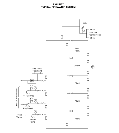
- The fire main system shall be designed as a grid, with loops along each of the four sides of process area blocks and where needed, install mains across the block between units to connect with perimeter mains. When calculating residual pressures, flow shall be assumed through all sections of the grid, with no portion out of service. Pressure drop calculations shall allow for flow to a given process unit area plus any additional flow required for other plant areas. Open end blinded tees shall be provided at the ends of grid sections where future extension of the fire main system is expected. The system shall be hydraulically balanced based upon the required firewater demand determined in accordance with this Practice.
- (*)Fire main system design calculations, layout and arrangement shall be subject to the approval of the Owner’s Engineer. For hydraulic calculation of pipe sizing a Hazen and Williams “C” factor of 100 shall be used. Where existing systems are to be expanded, the new additions shall be sized in accordance with a hydraulic model of the existing system. Pipe flow velocities shall not exceed 20 fps in any area of the piping distribution system. The fire main system layout and design shall provide the required water flow to all hydrants, water spray systems, monitors and foam systems.
- Labeling
- All lines shall be painted red.
- Operating instructions shall be installed at all fixed/semi–fixed foam and water cooling firefighting facilities.
- Fire Main Size and Rating
- Maximum working pressure at any point on the fire main system shall not exceed 165 psig. Relief valves shall be installed at the main pumps to prevent over-pressuring the fire main at low flow and to protect the fire pump. Fire mains shall be at least 8 inch NPS (nominal pipe size). Fire main laterals, limited to 400 feet, shall be a minimum of 6 inches when suitable for a known flow and future expansion is not anticipated.
- Firewater piping shall be located outside of tank dike walls. Where fire lines must cross tankage areas inside dike walls, piping shall be buried to provide protection from spill fires.
- Elevation: Fire mains shall be below grade in process areas, along the battery limits. This provides for access to the process unit and permits fire hydrants to be located immediately adjacent to the main. Below grade fire main piping also provides protection of the piping system from direct blast pressure damage. Where freezing conditions exist, fire lines shall be buried to a depth below the frost line or as specified by project documents. In nonfreezing location other than process and pressurized storage areas, fire mains may be located on sleepers above grade.
- (*)Fire lines buried in areas containing cathodically protected foreign structures shall normally be bonded into the cathodic protection system or otherwise protected against anodic/ cathodic interference damage. An above grade dry pipe system installation shall be provided in a freezing climate subject to the approval of the Owner’s Engineer. It shall be suitably sloped to drain valves and designed so that the above grade portion can be shut off and drained when not in use.
- Division Valves: Division valves shall be provided at grid intersections, at the center of long loops, and at the main fire pump feed. Division valves shall be located so that any section of the grid can be taken out of service and the grid still supply water through adjacent sections to protect all plant areas. No more than six fire protection devices (hydrants, monitors) or systems shall be removed from service at any one time. For buried piping, division valves shall be the indicating type, identified by permanent signs as to purpose, and protected against damage from vehicles. Plant equipment location and fire hydrant positions shall be reviewed to determine the minimum use of division valves to provide reliability. Block valves shall be provided near the main on branch lines feeding firefighting equipment other than for single fire hydrants. Block valves shall be in accordance with this Section.
- Connections: THE FIREWATER SUPPLY FROM THE FIRE PUMPS SHALL NOT BE PERMANENTLY CONNECTED TO ANY PROCESS OR FACILITY FOR OTHER THAN FIRE FIGHTING USE. This will prevent loss of firewater in the event of emergency. There shall be no possibility of the firewater system becoming contaminated with flammable gas, liquid, or other process materials.
- (*)The fire main system shall be pressurized to permit early discovery of line failures and leaks. Plant utility pumps may be used for this purpose with the approval of the Owner’s Engineer. The following points shall be considered when using utility pumps for pressuring the fire mains:
- A throttling orifice or flow control valve shall be installed in any cross–connection to limit the flow of utility water to the fire mains. Thus, there will always be sufficient fresh water for boiler feed or process water. Either a drop in fire main pressure or increased flow shall be used to automatically start the fire pumps.
- The water supply to 1-inch hose on utility stations in process areas should be provided from the utility water system, not from the fire main system.
- (*)Material: Steel pipe shall be used above grade; steel or ductile iron pipe shall be used below grade. Gray cast iron pipe is not permitted. Alternate materials may be considered for fire mains when tested under hydrocarbon fire conditions with documented results and specifically reviewed and approved by the Owner. Buried steel pipe shall be suitably coated and wrapped for corrosion protection per EP 10–3–3 and Section 10.0. Steel pipe and valves shall meet the requirements of NFPA 24. Cast iron division valves of the rising–stem type, regardless of pipe material, may be used above grade only with the approval of the Owner’s Engineer. Postindicator, UL–listed or FM approved valves shall be used for below grade installations. Nonrising stem is not permitted.
- (*)Installation: Each pipe length and fitting shall be protected against job weld metal, dirt, stone, and debris during the installation. Each section shall be flushed adequately to clear any debris before closing the division valve at the farthest point of construction. Installed sections of the fire main system, complete with hydrants, shall be hydrostatically tested to 150% of the maximum working pressure for two hours in the presence of the Owner’s Engineer. Buried lines shall be tested and inspected for leaks and properly coated. Dielectric testing of coated pipe shall be conducted prior to backfilling. All piping defects shall be repaired, as necessary, before backfilling. Results of all testing and inspection shall be recorded and submitted to the Owner’s Engineer.
- Fire Hydrant Locations and Sizes
- (*)Fire hydrants shall be located in process areas on 100 to 150-foot centers along accessways and roadways. Any portion of a unit shall be capable of being covered by a 2–1/2 inch hose stream with 250 feet of hose from adjacent hydrants. Hydrant locations shall be arranged to permit equipment to be reached from at least two opposite directions so that manual hose line approaches can be made from the upwind side. If possible, hydrants shall be positioned so that they may also be used to protect equipment in adjacent units or areas. Guardrails shall be provided when hydrants near a road or accessway are subject to vehicular damage in accordance with Figure 2. The Owner’s Engineer shall approve the use of alternative guardrail designs.
- (*)The smallest hydrant in process areas not adjacent to roadways shall be 4 inches in size, with two 2–1/2 inch hose connections and no pumper connection. All hydrants protecting a process area and located along a road or accessway shall be 6 inches in size, with a pumper connection and two 2–1/2 inch valved hose connections. Pumper connections shall be between 4 inches to 6 inches as specified by the Owner’s Engineer for local fire truck connections. Hydrants shall be spaced to provide protection from different directions of access.
- (*)Eight-inch hydrants with pumper connections shall be provided where three 2–1/2 inch hose connections are needed. This may occur in tank farms where fixed roof tanks are 150 feet in diameter or larger and where fire trucks producing over 1000 gpm are provided. The pumper connection shall be 4 inch to 6 inch as specified by the Owner’s Engineer for local fire truck connections. In other areas, the 6-inch hydrants, with suitably sized pumper connections, shall be strategically located to cover areas where foam may be required for fire fighting.
- Tank farm fire hydrants shall be sized and located in accordance with NFPA 11 for foam requirements, but no less than one hydrant for each tank quadrant.
- (*)Hydrants adjacent to cooling towers or in the vicinity of small hydrocarbon storage tanks shall be 6 inches in size with two 2–1/2 inch valved hose connections and one 4 inch to 6 inch pumper connection as specified by the Owner’s Engineer for local fire truck connections.
- Hydrants in plant administrative, shop and other non–process areas shall be located in accordance with NFPA 24. A 4-inch hydrant with two 2–1/2 inch hose connections shall be placed on 250 foot centers.
- (*)On piers and wharves using hose streams as the primary protection, hydrants shall be located on 100-foot centers. Wet barrel type hydrants may be installed, consisting of a 4-inch hydrant with two 2–1/2 inch hose connections, unless otherwise specified by the Owner’s Engineer for larger wharves.
- Cast iron Compression–Type Hydrants: Cast iron self-draining, compression–type hydrants shall be used in freezing climates. These hydrants shall be UL or FM approved. These hydrants shall be provided for a normal working pressure of 150 psig but may be used, subject to the vendor’s recommendation, where the service pressure exceeds 150 psig. They shall be provided with a replaceable “breakable” barrel section with minimal leakage design when closed. Loss of main pressure due to collision damage will then be prevented by automatic closure of the main valve if the above grade section is broken. Compression–type hydrants are not suited for installation on abovegrade fire mains but are designed for use with buried mains.
- When ordering hydrants, the following information shall be included in vendor quotes:
- Size and type (barrel construction) desired.
- Number of 2–1/2 inch valved hose connections, each valve with cap and chain. (For flexibility in fire fighting, hose valves shall be furnished on the outlets.)
- When required, the size 4 to 6 inch pumper outlet with cap and chain but without hose valve.
- Type of 2 1/2 inch and 4 to 6-inch hose thread. (Unless otherwise specified, NST will be used.)
- Desired direction in which hydrant operating nut should turn to open main valve. (Request one operating wrench or hand wheel per hydrant or the number of wrenches desired.)
- Depth of trench.
- Size and type of pipe or base connection of fire main.
- Color and type of paint desired.
- Wet Barrel Hydrants: Wet barrel hydrants shall be used in nonfreezing climates or where a dry pipe fire main is provided. Such hydrants are suited for installation on above–grade fire mains. Each hose connection shall be valved. The steel hydrants shall be designed in accordance with Figure 3A and Figure 3B , and the barrels shall be hot–dip galvanized after welding.
MONITORS
- General
Monitors shall be used when they can be located so as to protect more than one item of process equipment from their installed position, or where their use is more effective than a fixed water spray system for fire fighting. Monitors are effective for cooling fire-exposed equipment, as well as for fire intensity control. They can be used to flush burning flammable liquids away from equipment, provided care is taken not to spread the fire. Portable monitors provide additional flexibility in fire control operations and can be provided for supplemental water cooling.
- Limitations and Location Guidelines
- Water Monitors
Water monitors have the following limitations:
- Water streams will be limited in reach of protected equipment when opposing or cross wind is 10 mph or more.
- Reduced range of operation of up to 50% occurs in opposing or cross wind of 5 mph.
- Poor application or excessive use may overtax drainage facilities and/or spread fire from initial location. Water streams can be blocked by physical obstructions such as buildings, equipment or pipeways.
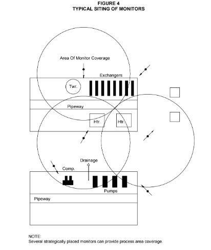
- Monitors shall be located as specified in Figure 4, for fire control, vessel cooling and/or fire extinguishment. Due to the limitations and unique advantages, the following factors shall be considered when locating firewater monitors:
- Monitors shall be placed so that there are as few physical obstructions to water streams between the monitor and protected equipment as possible.
- Wind conditions on the site shall be evaluated and monitors added in areas where shifting winds can block use of monitors or reduce effectiveness of protection.
- Monitors shall be positioned to use the advantage of prevailing wind where possible to increase the effective use of water streams.
- Monitors shall be located on the periphery of protected areas in positions that will be easily accessible in fire conditions with minimum exposure to operating personnel in fire condition.
- The minimum distance from protected equipment shall be 50 feet and the maximum distance shall be100 feet.
- Typical positions are depicted in Figure 4.
- Installation Requirements
- The minimum nozzle water pressure shall be100 psig.
- The quantity of water shall be 500 gpm to 1000 gpm. Capacities greater than 500 gpm should be used with discretion as the demand on the firewater system is high.
- The effective reach of monitors shall be150 feet horizontal at straight water stream or 120 feet for the center of a water spray pattern.
- Nozzles shall be adjustable, fog–to–straight stream nozzle for long range and for equipment or personnel exposure protection.
- See Section 9.5 for requirements regarding physical location of monitors.
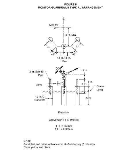
- Physical Protection: Where the monitor may be subject to being struck by vehicular traffic provide a guard rail such as that shown in Figure 5 shall be provided.
- The minimum water supply connection shall be an NPS 4 pipe to the nearest fire main for 500 gpm monitors. Four-inch feed connections shall be limited to distances up to 200 feet.
Multiple monitors supplied by a non–looped branch line, mains exceeding 200 feet or nozzle capacities exceeding 500 gpm shall be connected by 6-inch pipe. Shutoff valves at the monitor shall be NPS 4 ball–type. An indicator shutoff valve and automatic below grade drain valve shall be installed in freezing climates. All valves shall be clearly identified with weather resistant signs.
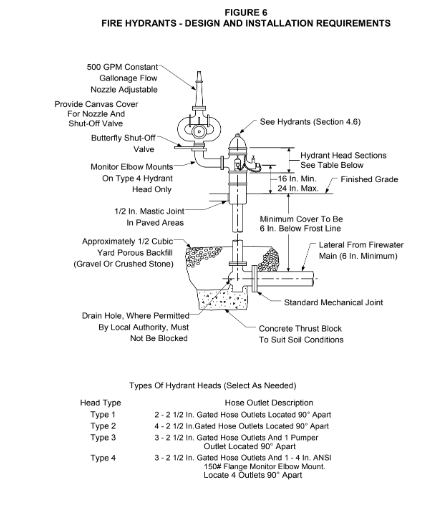
- Fire hydrant mounted monitors shall only be used where extensive piping or impairment of the firewater system will be required for installation and shall be in accordance with Figure 6. A strainer shall be installed ahead of the monitor, or self-cleaning, adjustable fog–to–straight stream nozzles shall be used where water supply is untreated or dirty.
- Portable Monitors
Portable monitors shall be provided in each plant as follows:
- At least two portable 500 gpm (minimum) monitors shall be provided in or near process units to supplement fixed firewater monitors.
- At least one 1000 gpm (minimum) foam water monitor shall be provided in the fire house or other alternate storage area for fighting tank and spill fires. This monitor shall be portable.
- Two 500 gpm foam water monitors shall be provided for spill fire fighting and shall be located in the fire house or in or near process or tank foam areas.
- Water Supply for Fire Monitors: Portable monitors shall be positioned near hydrants at the process area periphery. Monitors shall be provided with sufficient hose for connection to a hydrant when necessary for process area fire fighting. A 4-inch hydrant, suitably located or branch lines with two 2–1/2 inch connections and shutoff valves shall be provided from the fire main. The monitor shall be located away from spill fire potential areas on a gravel or concrete pad. The monitor shall be weather protected with a cover or shed root. Portable foam/water monitors will be arranged to use water from the fire main while hose connected to a fire truck for foam or water application. Foam/water monitors will not require strainers but water monitors equipped with adjustable fog–to–straight–stream nozzles shall have strainers when connected to untreated or dirty water services.
- Application
- Fixed or portable monitors shall be used for vessel surface cooling, fire intensity control, and/or fire extinguishment; see Table 2.
- Foam/water monitors shall be provided, when the plant is equipped with a foam truck, for the locations listed in Table 3.
10.0 TABLES
TABLE 1
PROCESS UNIT FIREWATER REQUIREMENTS
| Type of Process Unit | Minimum Firewater Demand (US gpm) |
|---|---|
| Atmospheric distillation, vacuum, or combination units with up to 100,000 bpcd throughput; treating plants; asphalt stills; others | 5000 |
| Atmospheric distillation, vacuum, or combination units with 100,000 bpcd or higher throughput; catalytic cracking units | 7000 |
| Light–end units containing volatile oils and hydrogen, such as reformers, catalytic desulfurizers, Fluid catalytic crackers, high pressure units (over 1000 PSI) | 9000 |
| Lube oil units and blending (excluding propane extraction units) | 4000 |
TABLE 2 FIREWATER MONITORS
| Type of Unit or Equipment | Application of Monitors |
|---|---|
| Process unit towers | Insulated column–type vessels, reboilers, hot oil piping and bottom connections. |
| Heat exchanger banks containing high–pressure volatile or hot materials. | Channel sections or expansion joints and flanged connections. |
| Process unit heaters | Exposed return bends and crossovers, areas under heaters, structure cooling and spill wash down. |
| Process unit air coolers | Coolers containing volatile liquids at over 250 psig or materials above autoignition temperature. |
| Offsite | Class I or II hydrocarbon service position offsite pumps. Position one or two fixed water monitors to cover both pumps and adjacent pipe manifolds. |
| Pipeways and sleeperways | Strategically placed fixed water monitors arranged to wash away spills and/or cool adjacent piping in event of fire under main pipeways and sleeperways vital to plant operation. |
TABLE 3 FOAM/WATER MONITORS
| Location | Application of Monitors |
|---|---|
| Process units | Minimum of two portable monitors provided for process area protection shall be foam/water type. |
| Tank fields | For fighting diked enclosure fires, pipeway fires, and cone roof foam solution application rate of 0.16 gpm/ft 2 of tank liquid surface area. A foam/water monitor shall be provided for use with a fire truck to apply foam on tank fires. |
| Piers and wharves | Fixed and portable foam/water monitors are recommended for fire protection on piers and wharves. At least one remotely controlled monitor should be installed. |
TABLE 4 DOCUMENTATION REQUIREMENTS
| Item | Description | Format | As–Built |
|---|---|---|---|
| 1 | Written approval to permit use of this Practice in place of a more stringent jurisdictional requirement. | See EP 2–5–2 | N/A |
| 2 | Results of a hazard analysis of the facility. | See EP 2–5–2 | N/A |
| 3 | Pre-fire plans. | See EP 2–5–2 | N/A |
| 4 | Fire systems calculations, layout and arrangement. | See EP 2–5–2 | Yes |
| 5 | Results of firewater system inspections and tests. | See EP 2–5–2 | N/A |
| 6 | Vendor quotes for hydrants. | See EP 2–5–2 | N/A |
11.0 FIGURES
© 2026 Inflection Point Engineering, LLC. All rights reserved. The content of this page — including calculation methods, reference data, written analysis, interactive tools, and source code — is the intellectual property of Inflection Point Engineering, LLC and is protected under applicable copyright, trademark, and trade secret laws. Unauthorized reproduction, redistribution, modification, or derivative use in whole or in part is prohibited without prior written consent.
Disclaimer. This material is provided for informational and educational purposes only and does not constitute professional engineering advice. Calculations, reference data, and methodologies are based on published standards and accepted engineering practice but are not a substitute for engineering judgment, site-specific analysis, or review by a licensed Professional Engineer. Inflection Point Engineering, LLC makes no warranties, express or implied, regarding the accuracy, completeness, or fitness for a particular purpose of any content presented here, and shall not be liable for any direct, indirect, incidental, or consequential damages arising from its use. Users assume all risk associated with applying this content to real-world design, operations, or decisions.
© 2026 Inflection Point Engineering, LLC. All rights reserved.