 Section 3 — Process Safety & Loss Prevention
Plant Layout
IPE Engineering Practice IPE-EP-3-2-1
Document number: IPE-EP-3-2-1 · Section: 3 — Process Safety & Loss Prevention
- Sewer Systems 21
- Utility Stations 21
- Roads and Accessways 21
- Interconnecting Pipeways 21
- Laydown and Storage Areas 22
- Railroad Facilities 22

SCOPE
- This Practice covers general requirements for the layout of process plants, associated offsite facilities and their equipment and structures where modifications and additions are being made to existing refineries. It is specifically applicable to conventional "outdoor" installations for processing, storing and handling flammable and combustible liquids and/or gasses and shall be used for both on site construction and modules fabricated off the site. It includes requirements for spacing between items of equipment or plants, clearances and access for construction, operation, maintenance, safety, and fire-fighting purposes.
- This Practice is intended to cover equipment layout requirements for new construction. As such, it is based on current industry codes and practices and lessons learned within the petrochemical industry .It is acknowledged that existing installations designed in accordance with earlier industry standards and practices may not comply with the requirements stipulated in this Practice. However, if the installation is judged by the Owner to be significantly different from these requirements (i.e. during a Process Hazards Analysis as required by OSHA 1910.119), then appropriate mitigation measures shall be provided. For existing equipment that is to be changed, a safety review of the facility design shall be conducted in accordance with EP 3–5–3.
- The Owner's Engineer shall specify if any of the requirements of this Practice are to be applied to any installations outside its stated scope. This may include plants processing hazardous materials other than flammable or combustible liquids and gasses (e.g. toxic materials).
- In many cases there will be local statutory requirements affecting plant layout that must be complied with. Where this Practice is more rigorous than such statutory requirements it shall be applied, unless specified otherwise by the Owner.
- Any deviation from this Practice must be approved by the procedure described in EP 1–1-3.
- An asterisk (*) indicates that a decision by the Owner or Owner’s Engineer is required.
2.0 REFERENCES
The latest edition of the following standards and publications are referred to herein.
STANDARDS AND PUBLICATIONS
| IPE Engineering Practices | IPE Engineering Practices |
|---|---|
| EP 1–1–3 | Deviations to IPE Engineering Practices |
| EP 3–5–2 | Firewater Systems |
| EP 3–7–1 | Pressure Relieving Systems |
| EP 3–7–2 | Relief Disposal Systems |
| EP 4–1–2 | Requirements for Blast Resistant Buildings and Structures |
| EP 4–5–3 | Auxiliary Structures for Operation and Maintenance |
| EP 4–10–1 | Roadways and Paving |
| EP 4–11–1 | Sewer Systems |
| EP 9–5–1 | Containment Dikes for Storage Tanks and Spheres |
| EP 13–1–1 | Power System Design Practices |
| EP 13–2–1 | Electrical Detail Design and Construction Practice |
| EP 5-1-2 | Piping Layout |
| ASME Code | ASME Code |
| B31.3 | Chemical Plant and Petroleum Refining Piping |
| API Standards | API Standards |
| RP 500 RP 521 RP 2508 RP 2510 |
Classification of Areas for Electrical Installations in Petroleum Refineries Guide for Pressure Relief and Depressurizing Systems Design and Construction of Ethane a 00 Ethylene Installations at Marine and Pipeline Terminals, Natural Gas Processing Plants, Refineries, Petroleum Plants, and Tank Farms Design and Construction of Liquefied Petroleum Gas (LPG) Installations |
| NFPA Standards | NFPA Standards |
| 30 214 |
Flammable and Combustible Liquids Code Water- Cooling Towers |
DEFINITIONS
- Accessways - Clear, unobstructed paths required to perform routine plant operations and maintenance within a process unit, storage or utility area.
- Autoignition temperature -The temperature at which hydrocarbons will ignite without any external source of ignition being present. This temperature varies with hydrocarbon type, but in the absence of definitive data should be taken as 410°F.
- Battery Limit - The boundary of a process unit enclosing all equipment and unit limit block valves.
- Combustible liquid - A liquid having a flash point (FP) at or>100°F .Combustible liquids are subdivided by NFPA-30 into:
- Class IIA - FP at or >100°F and <140°F
- Class IIB - FP at or >140°F and <200°F
- Class IIB - FP at or >200°F
- Complex - A group of process units, the operation of which is interlinked, e.g. a group consisting of a vacuum unit, catalytic cracker, alkylation unit and sulfuric recovery unit, controlled from a common control room.
- Critical Electrical Switch Racks - Electrical supply or control equipment whose loss or shutdown would interfere with the function of an emergency system, e.g. UPS, EBV, emergency lighting.
- Equipment - Includes vessels, compressors, heat exchangers, pumps, furnaces, valves, and drivers.
- Flammable liquid - A liquid having a flash point (FP) below 100°F and having a vapor pressure not exceeding 40 psig at 100°F. Flammable liquids are subdivided by NFPA -30 into:
- Class IA - FP <73°F, boiling point <100°F
- Class IB - FP <73°F, boiling point at or >100°
- Class IC - FP at or >73°F and <100°F
- Module - Any assembly of equipment items and their associated piping, instrumentation, electrical equipment, structure and fittings combined into a transportable subsection of a process unit or off site facility .The definition includes all sizes and sources of assembly, preassembled equipment items, i.e. towers, fired heaters, or piperack units.
- Non-Severe Service Equipment - Equipment operating below 410°F and 500 psig.
- Offsites -The units and equipment that are not specifically part of the processing units, but which provide a service to the process units. Offsites includes utilities (except within a process unit) and tankage.
- Owner -Inflection Point Engineering, LLC.
- Owner's Engineer - A Inflection Point Engineering, LLC appointed engineer.
- Plant - A general term used to describe anyone or all of the units on a given site.
- Plot - An area of the site containing one or more processing units, or tankage.
- Primary Roads - Roadways around the periphery of a process unit(s). Primary roads carry heavy, unrestricted traffic.
- Process Hazards Analysis - Those techniques used to determine the frequency and/or consequences of hazardous events and the effect on the surrounding environment.
- Process Unit - A main production component of a Plant, consisting of groups of equipment arranged to perform one or more process operations (i.e. crude distillation, catalytic cracking).
- Property Lines - The boundaries of the Owner's property adjacent to a public thoroughfare or adjacent to land which are, or may be, developed.
- Secondary Roads - Roadways used to gain access too less accessible equipment or equipment inside of a process unit's battery limits. Secondary roads carry restricted traffic, e.g. required for maintenance.
- Severe Service Equipment - Equipment operating at or above 410°F or 500 psig.
- Site - Any area where a new facility, e.g. Plant, gas liquefaction or processing plant, or storage terminal is to be built or an extension to existing facilities is to be provided.
- Special Fire Risk Area is defined as an area which:
- Lies within 25 feet of severe duty plant and equipment.
- Lies within 25 feet of hydrocarbon inventories in excess of 2000 gallons of flammable liquids or combustible liquids held at or above their flash point.
- Lies within a tank dike, or other low tying area designed to contain flammable materials, or combustible materials held at or above their flashpoint.
- Inside a building where flammable materials or combustible materials at or above their flash point, are being handled.
- Unit Switch Rack - Electrical supply and control equipment, including motor control centers, assembled into a self standing frame on a process unit, adjacent to the equipment being supplied.
- Spacing - The clear unobstructed horizontal and vertical distance between adjacent edges of equipment or plots. Spacing requirements may be specified in terms of vessel, exchanger, or other equipment diameters or straight-line distances. When different diameters of like equipment are considered for determining space requirements, the larger diameter shall be used. Spacing requirements to rotating equipment shall be measured to the equipment base. Spacing requirements between plots shall be measured to and from the plot battery limit.
GENERAL PLANT LAYOUT CONSIDERATIONS
- The layout of plant and equipment shall be consistent with prevailing atmospheric and site conditions, and accepted good engineering practices.
- The introduction of new plant and equipment onto existing plots is recognized as providing special problems as, in most cases, the original plot layout did not take into consideration any future expansion or modification. Therefore, it is necessary to institute a number of basic rules in order to make that fundamental decision as to whether the introduction of new facilities can be done without significantly increasing the overall level of hazard. This is called a risk-based approach rather than one purely based on consequences.
- The following basic rules shall be applied:
- Is there sufficient separation between sources of ignition and potential points of release of flammable materials? Sources of ignition include: fired heaters, road vehicles, railway locomotives, general purpose electrical equipment, and hot surfaces in excess of 1100°F. Potential points of release include: pump and compressor glandseals, sample points, tank vents, surface openings from underground drainage systems, atmospheric vents from relief valves/rupture discs. As a general rule: sources of ignition should be separated from potential sources of release by 50 feet. This is the basis of API RP 500, which specifically deals with electrical area classification. This Practice extends that logic to cover all sources of ignition.
- Is there sufficient separation between independently operated processes or equipment? The point here is whether one plant/facility can be safely maintained while the other is operating normally. A decision on what constitutes a safe separation is a matter of judgement, based on the type of maintenance to be carried out, the maintenance aids used (cranes, "cherry pickers", etc.), the size of equipment, parts to be used in the maintenance (e.g. furnace tubes. heat exchanger bundles, etc.). As a basic rule no maintenance work on one plant/facility should encroach within the hazardous area shadow of another independently operated unit. Also no vessel entry requirement on one unit should be within the hazardous area shadow of another independently operated unit.
- Is there sufficient separation to allow access for emergency response vehicles for foreseen major emergency events, e.g. fire, spillage, and potentially dangerous process excursions? This implies that as part of the decision making process, a pre-emergency assessment should be carried out to consider the implications of foreseeable, credible, emergencies on the new plant and equipment.
- Is there sufficient separation between populations of workers and plant hazards? Generally, a 50 feet separation rule should apply except where common control rooms are provided where larger distances may be appropriate by virtue of population size and critical mass of control equipment, see Section 8.0 of this Practice.
- Is there sufficient separation between independently operated units to prevent knock on of fire? In this case the rule should be that at least 100 feet, or a greater distance should separate special fire risk areas on adjacent units if required by a process hazards analysis.
- Is there sufficient separation to prevent potential health hazards from one unit affecting workers on an adjacent independently operated unit? This can mean both the exposure to workers from harmful chemicals, and the physical effects of operating plant (e.g. noise, relief devices venting to atmosphere).
- Is there sufficient separation to allow independently operated units to be operated and routinely started up and shutdown without unduly affecting the other? In addition to operator access, this can mean delivery of chemicals by forklift truck, uplifting of product, or supply of process consumables for start up (e.g. chemicals for catalyst activation/conditioning, etc).
- Do the new facilities unduly reduce access to emergency facilities such as safety showers, activation points for fired heater snuffing steam, and emergency block valve activation?
DEVIATIONS FROM THIS PRACTICE
- Any deviation from this Practice may be justified when the increased risk has been adequately compensated for by the provision of appropriate mitigation measures. Preferably, these mitigation measures should be justified on a cost benefit basis. However, this is not always easy and may involve complex calculation measures that may not have a high degree of confidence in the results. Accordingly .the mathematical approach should only be taken when cost/benefit is not immediately apparent, or when dealing with new technology. Established mitigation measures should always be considered first, for example:
- Increased passive fireproofing or fixed firewater spray systems should be considered if access in an emergency is a problem
- Remotely operated. Class 4 (see EP 5-1-2) emergency block valves should be considered where operator access in an emergency is seen to be a problem.
- Flammable gas detectors should be considered in areas where proximity to sources of ignition is seen to be a problem.
- Double mechanical seals should be considered where difficulties are seen in positioning severe service equipment.
- A safety review of all modifications to existing units including the installation of new equipment should be completed based on the Owners management of change and process safety review requirements.
PLOT LAYOUT
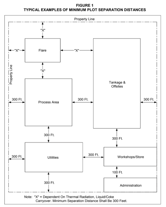
- This Practice is intended to cover new and modifications to existing process plots. There should not, therefore, be a need to consider the spacing of plots within the scope of this EP. If there is an issue of plot layout arising. The requirements of Figure 1 showing typical separation distances between plots should be met. When it is not possible to meet these requirements due to existing plant geography, a Process Hazards Analysis shall be conducted to confirm the acceptability of the proposed location.
- The basic shape of the plant shall remain unaltered. This means that process plant stays in the designated process plot, and is not installed in an administration, tankage, or dispatch plot; and vice versa.
- In the event that modifications to an existing unit extend beyond the battery limit of that unit the criteria contained in paragraph 4.3 shall be considered.
PROCESS EQUIPMENT LAYOUT AND SPACING
General
The layout and spacing of process equipment shall be determined by applying a set of rules based on paragraph 4.3 of this Practice that is summarized below. If a decision is taken to deviate from these rules, a full deviation request supported by a Process Hazards Analysis shall be provided.
- Equipment considered to be a source of release (e.g. compressors) shall be located no closer than 50 feet from a source of ignition such as a fired heater or unrestricted roadway. This requirement is consistent with the electrical hazardous area classification rules applied to process units.
- Facilities required to be operated in an emergency shall be no closer to the source of the emergency than 50 feet and shall also not be in a special fire risk area.
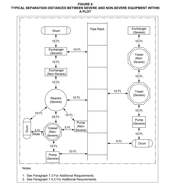
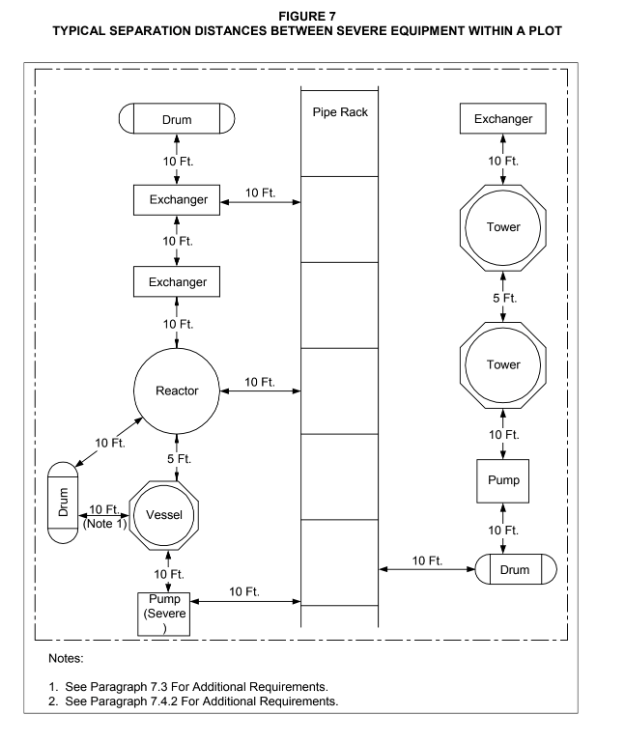
- The spacing of severe service equipment from other dissimilar equipment shall be a minimum of 10 feet. Separation of identical severe duty equipment (e.g. spare pumps) shall be a minimum of 5 feet.
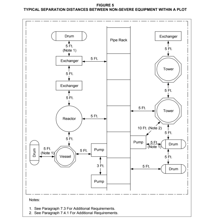
- The spacing of non-severe duty equipment from other dissimilar non-severe duty equipment shall be a minimum of 5 feet. Separation of identical items of non-severe duty equipment shall be a minimum of 3 feet.
- In all cases separation of equipment shall not impede access for operations, maintenance, or emergency response.
- Operations and maintenance access shall be a minimum of 3 feet clear space around each item of equipment.
- Typical layouts of severe and non-severe service equipment are included as Figure 5, Figure 6, and Figure 7 of this Practice.
Towers and Reactors
- General layout and spacing requirements for towers and reactors are:
- A tower or reactor shall be located adjacent to the unit pipe rack, as close as possible to related items such as pumps, reboilers, drums and condensers and shall be positioned to facilitate an efficient interconnection between itself and its associated equipment. There is no spacing requirement between a tower and its reboiler other than that normally required for adequate operation and maintenance access.
- A secondary road shall be provided for maintenance access.
- Access platforms and ladders shall be provided as required in EP 4-5-3.
- Severe Service Reactors (process at or above 410°F or 500 psig): In general, high temperature reactors shall be placed as close as possible to their associated heaters in order to minimize the length of high temperature piping runs. These reactors shall be spaced a minimum of 25 feet from equipment in non-severe service such as towers. Reactors in the same service may be placed a minimum of 5 feet apart provided adequate clearance for operation and maintenance is provided.
Drums
- Spacing between a drum and its associated tower, pump, exchangers, etc. shall be determined to allow access for operations maintenance and fire fighting.
- Blowdown and flare knockout drums shall be located in a separate area of the unit to avoid involvement in unit fires. These drums shall be placed a minimum of 25 feet from other process equipment and 50 feet from fired heaters.
Air Coolers
- Air coolers are generally supported from the central pipe rack adjacent to the associated equipment and are serviced by platforms at the header boxes and beneath the air coolers for motor maintenance. Air coolers shall be positioned to allow for interconnecting piping flexibility. Adequate space shall be made available for maintenance access by mobile cranes for the removal of air cooler tube bundles. No equipment shall be located over air fin fan coolers.
- Air cooled heat exchangers containing flammable liquids and gasses shall not be installed directly above control houses, switch gear houses, transformers, pumps handling flammable fluids, or other major credible potential leak sources of combustible material.
- Air coolers shall be separated by 10 feet minimum horizontal distance from exchangers operating at or above 410°F and 10 feet from pumps handling flammables at or above 410°F in order to minimize fire hazards associated with oil leakage on equipment operating at or above 410°F.
Shell and Tube Heat Exchangers
- Shell and tube heat exchangers shall be located so that when their tube bundles are withdrawn, they do not project into an emergency escape route or any road with unrestricted vehicle access.
- Shell and tube heat exchangers shall be arranged so that they can readily be dismantled for cleaning and maintenance. Also, the spacing between heat exchanger shells should allow sufficient unobstructed clearance for access for the bundle withdraw equipment, and to permit access for shell flange gasket renewal.
- The preferred arrangement for exchangers is in single tiers. If required, stacked exchangers shall not be more than 3 levels or over 12 feet above the ground or operating platform. Exchanger placement clearances shall be adequate to allow blinding, tube bundle removal, isolation and testing of stacked exchangers individually without disturbing the exchanger's supporting structure.
- General Requirements for heat exchangers operating below 410°F and 500 psig are shown below:
- Exchangers operating below 410°F and 500 psig on the shell side or tube side inlets shall have a minimum spacing of 5 feet from a tower operating in non-severe service. This requirement is based on operations and maintenance considerations only. The minimum separation of exchangers connected by common process streams or in dissimilar service is 3 feet.
- The minimum separation between these exchangers and pressure drums is 5 feet.
- General Requirements for heat exchangers operating above 410°F and 500 psig are shown below::
- Exchangers operating at or above 410°F or 500 psig either on the shell side or tube side inlets shall have a minimum spacing of 10 feet from a tower. This is required for fire fighting access. Spacing between a tower and its associated reboiler is based on operations and maintenance considerations only. The minimum separation of exchangers connected by common process stream is 5 feet. The minimum spacing between exchangers in dissimilar service shall be 10 feet.
- The minimum separation between these exchangers and pressure drums is 10 feet.
Fired Heaters
- A heater, or group of heaters, shall ideally be located on the periphery of a plot and immediately adjacent to an unrestricted road. Adequate access for fire fighting shall be provided for on all sides and, in the case of a group of heaters, they shall be separated from the remainder of the unit(s) by vehicular accessways on the other three sides of the group.
- The minimum recommended separation distances of fired heaters from process vessels and equipment handling flammable material is 50 ft. Where practical, fired heaters shall be located near battery limits or roadways with consideration given to the effects that adjacent units may have on the furnaces.
- The layout and design of heaters shall normally be such that the tube removal can be effected by mobile lifting equipment for which there shall be proper access.
- Heaters that may be shut down individually for turnaround require 25 feet spacing. Furnaces that may be shut down together for turnaround require only normal maintenance spacing.
- The top of a heater stack shall be at least 10 feet higher than any equipment within a horizontal distance of 200 feet.
- In addition to the minimum spacing requirements indicated above the following potential hazard sources shall be located a minimum of 50 feet horizontally from the heater and any associated electrical equipment:
- Sample points.
- Process, fuel line and other vents and drains open or opened to atmosphere during normal operation. This shall include drains from fuel and pilot gas knockout drums. However, outlets from vents and drains that are opened only during plant shutdown or infrequent maintenance may be less than 50 feet from a heater, provided they are closed and plugged during normal operation.
- All fuel gas and low-flash fuel control valves and meters.
- Filters on Iow-flash fuel supply lines.
- Fuel gas line filters.
- Pilot gas line filters.
- The potential hazard sources shall also be located not less than 50 feet from any process or utility lines that can operate at 1100°F or more. This includes transfer lines to or from heaters, and gas turbine exhausts. Surface drains shall not be located directly under a heater.
- Fuel gas knock out drums shall be spaced as close as possible to their respective heaters, but restricted to a minimum of 25 feet and provided with closed drain connections.
- Equipment handling nonflammables may be spaced 15 feet from heaters with the exception that equipment higher than 10 feet be spaced 25 feet from heaters having liquid in the tubes.
Onsite Tanks
Atmospheric storage tanks containing flammable liquids inside process unit battery limits shall be less than 5,000 barrels capacity and diked in accordance with NFPA 30. Onsite tanks shall be located at least 50 feet from process equipment identified as a source of ignition. Process equipment shall not be located inside the diked area.
Piping
- General
- General requirements for above and below ground piping are covered in EP 5-1-2.
- The piping layout should minimize piping runs on very high pressure and corrosive/toxic services such as acid gases. Piping on these duties shall, wherever possible, avoid overhead crossings of designated vehicle accessways. Pipe trenches shall not be used.
Pipe Racks
- Piping above grade shall be consolidated into pipe racks and routed through the unit area in such a manner as to offer minimum obstruction to maintenance operations and fire fighting. Piping from other process units or offsite operating areas shall not be routed on onsite pipe racks unless they terminate at the unit served by the onsite pipe racks. Internal unit piping shall not be run on offsite racks.
- In complexes, common utility pipe work, e.g. flare lines, shall be routed away from severe duty equipment.
- Lateral pipe racks interconnecting two parallel pipe racks shall be at least 80 feet apart if the laterals cross major accessways. This provides space for raising and lowering crane booms.
- Process equipment shall not be placed directly under pipe racks unless it can be clearly identified that the hazard is insignificant or has been adequately mitigated. Additionally, any new process equipment must not impede access for operations maintenance and fire fighting. Non process equipment such as switch racks may be located below pipe racks provided the above criteria are met.
- Pumps handling flammable materials at or above 410°F or above autoignition temperature shall be spaced a minimum of 10 feet between the edge of an overhead pipe rack and the nearest part of the pump. For pumps handling flammable materials below 410°F or below autoignition temperature, there are no minimum spacing requirements for pump drivers except those for maintenance access by way of mobile equipment. Clearance requirements for mobile equipment are covered in paragraph 14.4.
Pumps
- Pumps in Non-Severe Service Operating Below 410°F and 500 psig :
- In general, pumps operating below 410°F or autoignition temperature can be located at a minimum spacing of 10 feet from other non-associated equipment because these pumps do not present as great a fire risk as those in severe service. For pumps operating below 410°F and handling Class II materials at temperature less than 15°F below their flash point. Reduced spacing can be considered because such services represent a lower fire risk. Spacing to drums, and exchangers operating below 410°F or autoignition temperature shall be based on maintenance and personnel access.
- Pumps operating in the same service (e.g. spares. etc.) may be placed 3 feet apart for operating and maintenance access.
- Non-severe duty hydrocarbon pumps shall not be placed directly below air coolers or major process pipe racks.
- Non-severe duty pumps in utility service (e.g. water) shall be located using these same criteria unless otherwise directed by the Owner's Engineer.
- Pumps in Severe Service (Operating at or above 410°F or 500 psig):
- Pumps in severe service shall generally be located in the open, at or near grade level. All pumps shall be accessible for operation, maintenance and fire fighting. Adequately ventilated shelters shall be provided for large machines requiring in situ maintenance. Adequate space for lifting and handling facilities for maintenance shall also be provided.
- The seals of hydrocarbon pumps in severe service operating at a temperature higher than autoignition temperature of the pumped fluid shall not be located within 10 feet horizontal distance from air coolers on the outer edge of major unit piperacks.
- In addition, pumps in severe service shall not be located beneath other equipment such as towers, or drums. The preferred location of pumps is on the opposite side of towers away from fired heaters, fin-fans and pipe racks by the recommended minimum spacing requirements.
- In general, pumps operating at or above 410°F or above the autoignition temperature shall be separated from unassociated equipment by a minimum of 10 feet. Pumps operating in the severe service (e.g. spares, etc.) may be placed 5 feet apart. However, the minimum spacing requirement between the pump row and other equipment in non-severe service shall be maintained at 10 feet.
Compressors and Auxiliary Equipment
- The relative minimum spacing requirements between gas compressors and other equipment is 50 feet.
- Where there are several large compressors in a unit it is usually economical for operation and maintenance to locate them in one area. Associated intercoolers, knockout drums, pumps, etc. may be located in the compressor area and need not comply with minimum spacing to non- associated equipment provided they do not restrict access for fire fighting and maintenance. Compressors shall be oriented as follows:
- The ends of reciprocating compressor cylinders shall not be pointed toward control rooms, control centers, or operator shelters.
- The plane of rotation of centrifugal parts (rotors, turbines, etc.) shall not be in line with control rooms, control centers, or operator's shelters.
- Compressors and auxiliary equipment shall be located in an area for common operation and maintenance .If a surface condenser and condensate pumps are required, the condenser may be k>cated beneath the turbine if it is servicing one turbine. For multi-turbine drives, the condenser shall be located adjacent to the machines it services. In both cases, adequate room mus1 be provided for tube bundle removal.
- The associated condensate pumps shall be located as close as possible to the condenser, allowing adequate connecting piping flexibility .The lube and seal oil consoles shall be located as close as possible to the compressor with operator access provisions on all sides of the skid. Lube oil and seal consoles shall not be located under the compressor structure. Space must also be provided for removal of oil cooler tubes, control valves, pumps, and filters. Adequate space shall also be provided around the turbine and compressor for platforms.
- Vents from seal and lube oil reservoirs shall be routed to a place remote from the compressor and its auxiliaries.
- Fixed fire fighting systems on lube and seal oil consoles shall be capable of being remotely operated at least 50 feet away from the compressor.
- Access for fire fighting must be available on at least two sides. The possibility of massive mechanical failure in relation to surrounding equipment shall be considered in the layout and orientation of the compressor. A Process Hazards Analysis shall be conducted if the hazard is perceived to be particularly severe.
- Compressors handling inert gasses or air may be spaced closer than is shown for gas compressors, unless they are in a service critical to plant operations such as main plant instrument and air systems.
- Compressors driven by turbines or motors less than 200 HP shall be treated as pumps for spacing and location purposes. Where steam or motor drives are used, spacing is required only to permit operation and maintenance.
Safety Showers and Eyewash Facilities
- Process units containing corrosive chemicals, such as Hydrofluoric Acid (HF), Sodium Hydroxide (NaOH), Sulfuric Acid (H2S0J, Chlorine (CIJ, or Ammonia (NHJ, in which personnel operate and maintain equipment shall be provided with safety showers and eye baths. Safety showers and eye baths shall be located within a maximum distance of 25 feet from equipment containing or processing corrosive chemicals and clearly marked and well lit.
- A safety shower and eyewash station shall be located at all unit and complex control rooms and operator shelters.
Equipment In Non-Flammable Service
Spacing is primarily provided for operating and maintenance access with special consideration given to safety clearances for chemical, corrosive or toxic material handled.
OPERATIONS CENTERS
General
Control houses, control rooms and operator shelters are all population centers in close proximity to process plant. The emphasis should be twofold:
- Protecting personnel and control equipment from the effects of a process incident arising from the release of flammable and/or toxic materials.
- Providing an acceptable working environment for people and equipment in close proximity to operating plant.
It is an essential safety requirement to minimize the numbers of people housed in buildings close to process plant, consistent with safe operations and maintenance of the facility.
Central Control Buildings
These house the control and safety systems for the entire process area and are considered vital for the continued operation of the plant. As such, they should be a minimum of 300 feet from the process plant, and protected against blast in accordance with EP 4-1-2. These buildings shall also be protected against entry of toxic gasses by having an air intake located in a safe location with gas detection and alarm located in the intake duct. Provision shall be made to turn off the air intake fan(s) should toxic gas be ingested. The maximum credible blast overpressure and toxic gas concentrations shall be confirmed through a Process Hazards Analysis.
Control Centers/Houses
These house the control and safety systems for a single process unit or a group or complex of units. Separation of these Control Centers from the nearest process unit (which may not be the unit whose controls are housed in the building) should be a minimum of 50 feet, and protected against blast and the ingress of toxic gasses as described in paragraph 8.1.
Control Rooms/Operator Shelters
These are buildings that act as control centers for single small operating plants, and/or provide accommodation for outside operators. These should be windowless and pressurized buildings located at least 50 feet from the process plant, protected against blast and toxic gas entry.
Where the accommodation is required to be nearer than 50 feet to the process unit, the degree of pressurization shall be in accordance with electrical area classification for Class 1, Division 2 area, or else all of the electrical equipment within that building must be in accordance with this requirement. All normally manned buildings shall be no closer than 25 feet to any process plant, equipment, or pipe racks, and protected as described in paragraph 8.3.
Motor Control Centers/Process Unit Sub-stations/Switchracks
These are not normally manned buildings and, therefore, do not require the same level of protection. There are two considerations:
- MCC's/Sub-stations supplying a single process unit, located on that unit. These shall be located on the periphery of the unit and contain electrical equipment in accordance with the electrical area classification requirements for that unit.
- MCC's/Substations supplying more than a single process unit. These should be located at least 50 feet from the nearest process unit, and be windowless and pressurized to achieve general purpose. They should be designed such that their response to an incident on one process unit does not escalate that incident to other units.
Switchracks located on process units should be in accordance with the electrical area classification of that unit. They should not be located in a special fire risk area or in positions where they can impede access to process plant and equipment for operations maintenance and emergency response.
UTILITY EQUIPMENT - LAYOUT AND SPACING
Boilers and utility equipment shall be spaced to prevent exposure to fire or explosion damage. Equipment within the utility plant area, control rooms, feedwater pumps, deaerators and so forth may be spaced in accordance with good engineering judgment. Fuel oil day tanks, fuel oil pumps and heat exchangers shall be spaced at least 25 feet away from other utility equipment.
Steam Generating Equipment
Major steam generating equipment such as boilers shall be separated from possible sources of explosion that may disrupt the supply of steam to processing units by a minimum distance of 150 feet. Waste heat steam generators that are part of a process unit shall be spaced in accordance with the requirements for fired heaters, see paragraph 7.6 of this Practice.
Cooling Towers
- Cooling towers constructed from combustible materials shall be located at least 100 feet from process equipment.
- The direction of the prevailing wind shall be considered in selecting the location of Cooling Towers. The Cooling Tower shall be located to minimize any nuisance, both within and outside of the site, from water blowout, evaporation, corrosion, visibility problems on roadways and adjacent structures, snow drift and ice formation.
Firewater Pump Houses or Tanks
Firewater pumps or tanks shall be at least 300feet from processing, storage and loading areas where a major fire could occur, to avoid any such fire affecting the pumps.
Plant Air and Instrument Air Compressors
When in a central location, plant air and instrument air compressors may be adjacent to the boiler area. Instrument air compressors in vital service shall be separated by at least 100 feet from fired steam boilers and power generators. Instrument air compressors may be located at control houses provided a safe source of air is furnished.
Effluent Treatment Facilities
Effluent treatment facilities shall be located remote and downwind of ignition sources, with a minimum separation distance of 150 feet from process and storage areas. The facilities shall be located to maximize gravity flow.
STORAGE TANKS - LAYOUT AND SPACING
AtmospherIc Storage Tanks
- Minimum spacing between tanks, between tanks and property lines, and between tanks and public ways shall be in accordance with NFPA 30, Chapter 2, with the following exceptions:
- Tanks, other than crude tanks: Spacing between shells shall be a minimum of one-half the diameter of the larger tank.
- Crude tanks: Spacing between tank shells shall be 1-1/2 diameter up to a maximum distance of 350 feet.
- Hot oil tanks heated above 250°F excluding high-flash asphalt: Minimum spacing, shell to shell, shall be equal to the diameter of the larger tank.
- Slop oil emulsion-breaking tanks: Minimum spacing, shell to shell, shall be equal to the diameter of the larger tank.
- Pumps associated with tankage operations shall not be located inside the dike area of a tank, and shall preferably be grouped together with separation of individual pumps in accordance with paragraph 7.9.
- The minimum spacing between tankage and associated pumps shall be 50 feet.
- Tanks shall be laid out to provide access for fire fighting. For tanks 75 feet in diameter or larger, there shall be no more than two rows of tanks between adjacent access roads. Tanks 300 feet in diameter or larger shall be arranged in single rows between access roads. Tanks less than 75 feet in diameter shall be arranged in accordance with NFPA 30 requirements.
Refrigerated Storage Tanks
- Minimum spacing shall be as follows: Refrigerated storage tanks shall be located at least 150 feet to 300 feet from process units and 150 feet from flammable liquid storage tanks. These tanks shall be placed a minimum of 400 feet from property lines, normally occupied buildings, flares, fired heaters, or similar fixed source of ignition. Spacing between refrigerated storage tanks shall be at least half the diameter of the largest tank for tanks less than 50 feet in diameter. For tanks greater than 50 feet in diameter, the spacing between tanks shall equal the diameter of the largest tank.
- The distance from the property line to the centerline of the dike wall surrounding a refrigerated tank shall not be less than 100 feet at any point.
Pressurized Storage Tanks
- The spacing for cylindrical storage tanks (i.e. bullets) shall be as follows:
- Minimum spacing between cylindrical storage vessels containing hydrocarbons and other plant facilities shall be as follows:
- From occupied buildings, process units, and continuous ignition sources such as process unit heaters or flares: 300 feet.
- From atmospheric flammable liquid storage: 150 feet (Exception: The recommended distance from atmospheric storage tanks of less than 15,000 bbl capacity is 50 feet.)
- Minimum spacing between cylindrical storage vessels shall be in accordance with API 2508 and API 2510 as applicable if fixed watersprays or other means of exposure protection is provided. If only fire monitors are provided for exposure protection, the required spacing shall be twice that required by the API standards.
- Spacing between cylindrical storage vessels and property lines shall be 200 feet for tanks of less than 5000 gallons capacity and 400 feet for larger tanks.
- The hemispherical heads of storage vessels shall not point directly at process or tankage plots or populated areas.
- The spacing for pressure storage spheres shall be as follows:
- A minimum of 350 feet shall be required between spheres and the property line, normally occupied buildings or any continuous source of ignition such as a process furnace or fired boiler. The distance from the base of a flare shall be at least 300 feet.
- A minimum of 150 feet shall be required between pressure storage spheres and atmospheric storage tanks containing flammable products.
- Spacing between spheres shall be at least one tank diameter, but not less than 50 feet.
FLARE AREA -RELATIVE SPACING
Elevated Flare Stacks
- The location, spacing, orientation, and height of flares shall be determined, for the particular site by a full assessment of the factors involved, including radiant heat exposure, burning liquid fallout, incandescent particles and pollution considerations.
- Elevated flares shall be at least as high as any platform within 500 feet horizontally, and in no case less that 50 feet high, except for low-pressure flares associated with refrigerated storage, which shall be at least 25 feet high.
- Any source of ignitable hydrocarbons other than the flare knockout drum and associated pumps shall be at least 300 feet from the base of the flare stack. The knockout drum and pumps shall be at least 50 feet from the flare stack.
- Flare location and height must meet all applicable standards for atmospheric pollution by combustion products and noise control.
- Flare elevation and spacing must not exceed permissible radiant heat densities for personnel at grade under conditions of maximum heat release. Flare elevation and spacing may be governed by radiant heat exposure of equipment.
- Flares shall be located to limit the maximum ground level heat density to 500 BTU's per hour per square foot at the edge of the plot. The minimum distance from the base of the flare stack to the property line or adjacent plot shall be at least 300 feet or height of the flare stack.
- Two or more flares that are to be taken out of service independently for maintenance shall be separated by at least 500 feet. Where required, based on radiant heat calculations, platforms and ladders shall be shielded to permit escape from the effects of radiant heat from a potential large release from flares in service.
Ground Flares and Thermal Oxidizers
- Ground flares and thermal oxidizers shall be located at least 250 feet from other plant facilities. Additional spacing may be required based on radiation considerations.
- Fencing shall be provided where required for radiation protection and access control.
12.0 ADMINISTRATION AND SUPPORT BUILDINGS - RELATIVE SPACING
- Administrative offices shall be located at least 50 feet from maintenance shop buildings.
- Buildings within the administration and support plot shall be separated as required by the applicable building code in effect.
- Laboratories shall not be located in the same building as administrative offices.
LOADING AND UNLOADING FACILITIES - RELATIVE SPACING
Petroleum Piers and Wharves
The minimum spacing requirement between a pier and wharf and process units is 300 feet in order to protect plant equipment from dock fires. Minimum spacing requirements between adjacent piers and wharves are determined by site-specific operational requirements.
Loading Racks
- Access from the site boundary to and from the racks shall, preferably, be separate from the main access to the site, and shall be located to minimize traffic through process areas.
- Loading/unloading areas for road transport shall have adequate space for access for filling, parking, and maneuvering. A drive-through rack arrangement shall be provided.
- Loading/unloading areas for rail transport shall include adequate spur tracks for standing, filling, shunting.
- Where loading and unloading racks handle bulk flammable or hazardous raw materials or products, these facilities shall, preferably, be consolidated in a single remote area on the periphery of the site. This area shall be clear of roads, railways and concentrations of personnel, where any of these are not directly associated with the loading or unloading operations.
- The loading and unloading facilities shall be downwind or crosswind from process units and sources of ignition based on the prevailing wind.
- Unloading racks for non-flammable materials (acids, catalysts, etc.) for use in the process may be located at the edge of the process area unit.
SITE-WIDE SYSTEMS AND FACILITIES
Plant Firewater
The layout and arrangement of the plant firewater system shall be in accordance with EP 3-5-2.
Sewer Systems
The layout and arrangement of plant drainage and sewer systems shall be in accordance with EP 4-8-1.
Utility Stations
Utility stations shall be located at regular intervals and at known points of use in process units and offsite areas as required, and clearly marked.
Roads and Accessways
- Primary roadways shall be at least 25 feet wide and have a clear height of 22 feet. Secondary roadways shall be at least 15 feet wide and have a clear height of 22 feet.
- The required width of an accessway shall be 36 inches wider than the widest vehicle it will serve. The minimum clearance height for accessways shall be 12 feet. Accessways may be run longitudinally under piperacks provided adequate clearance is available for the tallest vehicle it will service.
- Vehicular accessways shall be as straight as practicable and free of overhead structures except where piperacks, ducts and/or conveyors are located. Accessways should not cross main drainage systems and cable trenches. Equipment shall not protrude into accessways.
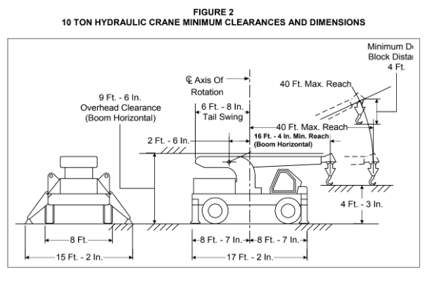
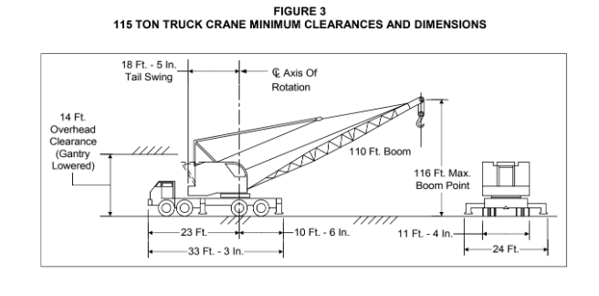
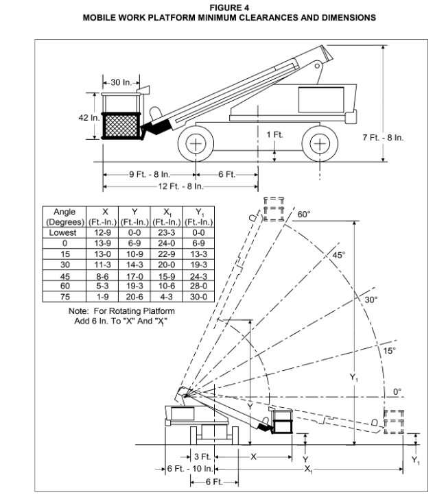
- Where overhead piperacks, ducts, or other obstructions cross a road or accessway, the space available horizontally at grade and overhead shall permit access of the largest crane or mobile equipment required for maintenance work or emergency services. When a crane will be used for maintenance work, clearance shall be maintained to allow maneuvering of the crane to the required position and the raising and extension of the jib without overhead obstruction. Required clearances for various sized cranes are provided in Table 1 and Table 2 and Figure 2, Figure 3 and Figure 4 of this Practice. The safe loads indicated in Table 1 and Table 2 are approximate and shall only be used in determining minimum clearances. The crane manufacturer shall determine the actual safe loads. The following minimum clearances should be provided for process unit accessways:
- Under pipe racks, provide clear space to permit a 10-ton hydraulic crane to gain access to pumps for routine maintenance and removal.
- To reactors, provide clear space for catalyst transfer vehicles to reach the area where the catalyst transfer nozzles are located.
- At compressors, provide enough clear space to permit service vehicles (e.g. a flat bed) to enter the Drop Zone- and remove components with mobile or permanent handling facilities.
- Around equipment in dirty service, provide clear space for the performance of frequently required maintenance.
- At exchangers, provide adequate clear space for the removal of tube bundles.
Interconnecting Pipeways
- Piping which interconnects process units shall be located on one or more central pipeways that are outside of the battery limits of individual process areas. The minimum spacing between interconnecting pipeways and equipment in severe service (over 410°F or 500 psig) shall be 50 feet. The minimum separation distance from non-severe service equipment shall be 25 feet.
- Main pipeways connecting process units, storage tanks, and loading and unloading facilities shall be located outside of tank diked areas.
- Pipe trenches shall not be used for interconnecting pipeways in new facilities.
Laydown and Storage Areas
- Laydown areas shall be provided as required for removal and replacement of equipment in process and offsites areas.
- When suitable, the separation space between plots or process units can be used for equipment laydown and temporary storage during turnarounds.
Railroad Facilities
- Railroad main lines shall be located at least 300 feet from process equipment and pressurized refrigerated and flammable liquid storage.
- The minimum recommended spacing between railroad spur and process units is 50 feet except for spurs servicing coker units. The minimum recommended spacing to offsite equipment is 25 feet, but greater distances may be required if required by a Process Hazards Analysis.
15.0 TABLES
TABLE 1
WORKING RANGES AND SAFE LOADS 10 TON HYDRAULIC CRANE
| Radius (Ft.) | Boom Point Elevation (Ft.) | Boom Point Elevation (Ft.) | Safe Load For 360° Rotation Lbs. (1) (2) | Safe Load For 360° Rotation Lbs. (1) (2) | Safe Load For 360° Rotation Lbs. (1) (2) |
|---|---|---|---|---|---|
| Radius (Ft.) | Boom Point Elevation (Ft.) | Boom Point Elevation (Ft.) | Without Outriggers | Without Rigger Fully Extended | Without Rigger Fully Extended |
| Radius (Ft.) | Minimum Boom | Maximum Boom | Without Outriggers | Minimum Boom | Maximum Boom |
| 10 | 23 | 49 | 12,000 | 20,000 | 16.000 |
| 12 | 21 | 48 | 8,600 | 18,000 | 16,000 |
| 15 | 16 | 47 | 5,800 | 16.000 | 14,000 |
| 20 | - | 44 | 3,900 | 10,000 | |
| 30 | - | 35 | 1,700 | 5,900 | |
| 40 | 8 | 3,300 |
NOTES:
1.) All load handling devices and boom attachments are considered part of the load and suitable allowance must be made for their combined weight.
2.) The safe loads Indicated In this table are approximate and shall only be used in determining minimum clearances. The crane manufacturer shall determine the actual safe loads.
TABLE 2
WORKING RANGES AND SAFE LOADS 115-TON TRUCK CRANE
| Radius (Ft.) | Boom Point Elevation (Ft.) | Safe Load For 110 Foot Boom (Lbs.) (1) (2) | Safe Load For 110 Foot Boom (Lbs.) (1) (2) | Safe Load For 110 Foot Boom (Lbs.) (1) (2) | Safe Load For 110 Foot Boom (Lbs.) (1) (2) |
|---|---|---|---|---|---|
| Radius (Ft.) | Boom Point Elevation (Ft.) | 18,500 Lb. Counterweight Without Outriggers Tires At 100 Psi |
18,500 Lb. Counterweight Without Outriggers Tires At 100 Psi |
With Outriggers Fully Extended |
35,500 Lb. Counterweight With Outriggers Fully Extended |
| Radius (Ft.) | Boom Point Elevation (Ft.) | Over Side | Over Rear | With Outriggers Fully Extended |
35,500 Lb. Counterweight With Outriggers Fully Extended |
| 25 | 116 | - | - | 105,000 | 117,000 |
| 30 | 115 | 23,000 | 28,000 | 77,000 | 93,000 |
| 35 | 114 | 19,000 | 22,000 | 61,000 | 74,000 |
| 45 | 110 | 13,000 | 16,000 | 41,000 | 51,000 |
| 60 | 103 | 8,300 | 10,000 | 27,000 | 34,000 |
| 70 | 97 | 6,200 | 8,200 | 22,000 | 27,000 |
| 80 | 89 | 4,600 | 6,400 | 18,000 | 22,000 |
| 100 | 64 | 2,500 | 3,900 | 12,000 | 16,000 |
| 110 | 41 | -. | - | 11,000 | 14,000 |
NOTES:
1.) The Ratings shown are based on freely suspended load and make no allowances for wind effect on lifted loads, ground condition, out of level operation, operating speed or other conditions that are detrimental to the safe operation of the crane.
2.) The safe loads Indicated In this table are approximate and shall only be used in determining minimum clearances. The crane manufacturer shall determine the actual safe loads.
16.0 FIGURES
SCOPE
- This Practice covers the drafting requirements for new piping isometric drawings created by Computer Aided Design (CAD) or manual method.
- Any deviation to this Practice must be approved by the procedure described in EP 1–1–3.
- An asterisk (*) indicates that a decision by the Owner or Owner’s Engineer is required.
2.0 REFERENCES
The latest edition of the following publications are referred to herein.
STANDARDS AND PUBLICATIONS
DEFINITIONS
- CAD Supervisor - Inflection Point Engineering, LLC employee responsible for all CAD services and drawings at each plant.
- Owner - Inflection Point Engineering, LLC.
- Owner’s Engineer - A Inflection Point Engineering, LLC appointed engineer.
PIPING ISOMETRIC DRAWINGS
- (*)The size of piping isometric drawings is site–specific and will be specified by the Owner’s Engineer. Generally, they are 11” X 17” or 18” X 24”.
- The piping isometric north arrow shall be oriented as specified by the CAD Supervisor.
- (*)The isometric drawing shall include a bill of materials located on the right hand side of the drawing or on a separate drawing as specified by the Owner’s Engineer. The associated line
number must be referenced in the drawing title block for all bill of materials drawings.
- (*)The bill of materials shall include the following items as a minimum. Additional items shall be approved by the Owner’s Engineer.
- Itemized description of piping and components.
- Quantity of each component.
- Size (appropriate dimension) of each component.
- Weight or schedule of flange or pipe, respectively.
- Rating, bore and face or end type of flange or fitting component, respectively.
- IPE Code Number for each component (see EP 5–2–3).
- Identify “shop” and “field” fabricated piping.
- The isometric drawing shall include the Owner’s standard title block (see EP 2–3–2).
- (*)Provisions shall be made to include supplemental information in addition to the standard title block. Supplemental information shall include the following items. Additional items shall be approved by the Owner’s Engineer.
- Service
- Line number, size, line specification (and insulation class, if not already part of the line number code)
- Design and operating pressure and temperature
- Hydrotest pressure
- Other test media and pressure (if applicable)
- Insulation and jacketing requirements
- Stress relieving requirements
- Heat trace requirements (if not already part of the line number code)
- Color code, plant area/Unit numbers
- Painting specifications
- Reference drawings and revision numbers
- Radiograph requirements (if applicable)
- Pipe spools to be shop and/or field fabricated shall be clearly identified on all piping isometric drawings. In addition, any field welds shall be identified on the piping isometric drawings.
© 2026 Inflection Point Engineering, LLC. All rights reserved. The content of this page — including calculation methods, reference data, written analysis, interactive tools, and source code — is the intellectual property of Inflection Point Engineering, LLC and is protected under applicable copyright, trademark, and trade secret laws. Unauthorized reproduction, redistribution, modification, or derivative use in whole or in part is prohibited without prior written consent.
Disclaimer. This material is provided for informational and educational purposes only and does not constitute professional engineering advice. Calculations, reference data, and methodologies are based on published standards and accepted engineering practice but are not a substitute for engineering judgment, site-specific analysis, or review by a licensed Professional Engineer. Inflection Point Engineering, LLC makes no warranties, express or implied, regarding the accuracy, completeness, or fitness for a particular purpose of any content presented here, and shall not be liable for any direct, indirect, incidental, or consequential damages arising from its use. Users assume all risk associated with applying this content to real-world design, operations, or decisions.
© 2026 Inflection Point Engineering, LLC. All rights reserved.