 Section 2 — Documentation Requirements
Supplemental Requirements for
IPE Engineering Practice IPE-EP-2-3-3
Document number: IPE-EP-2-3-3 · Section: 2 — Documentation Requirements
SCOPE
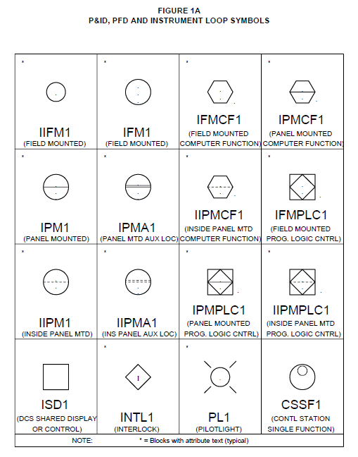
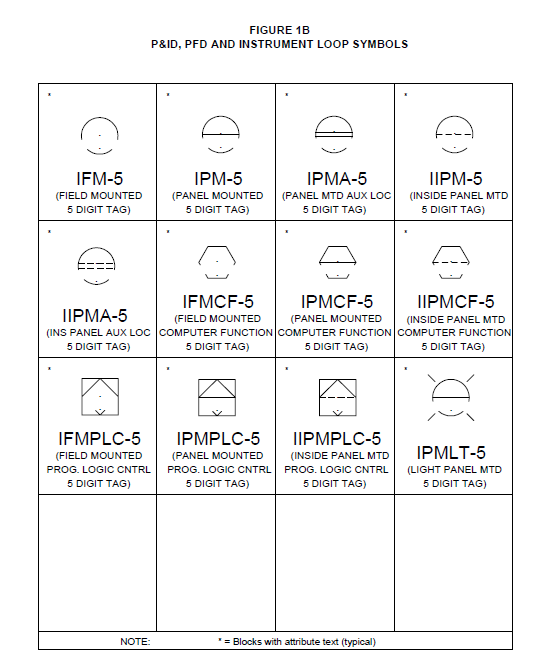
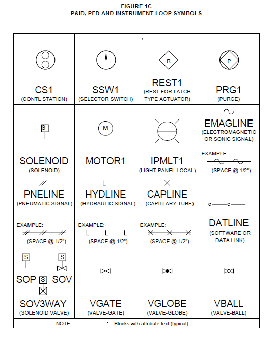
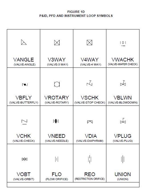
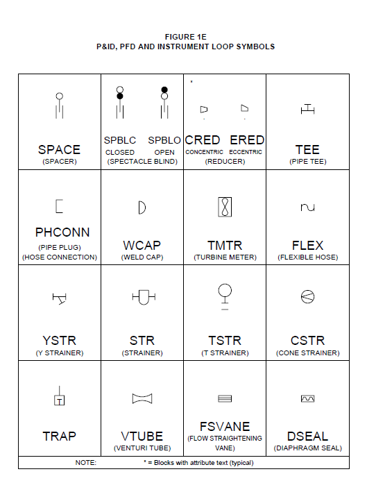
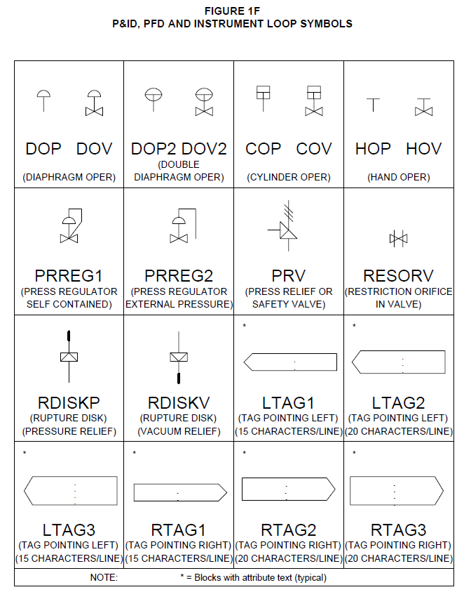
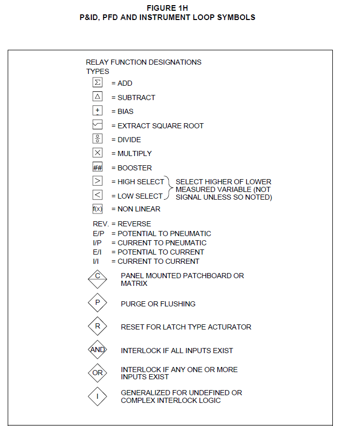
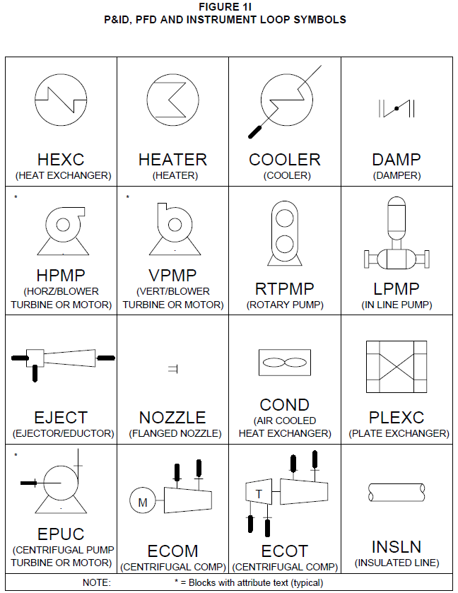
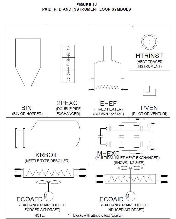
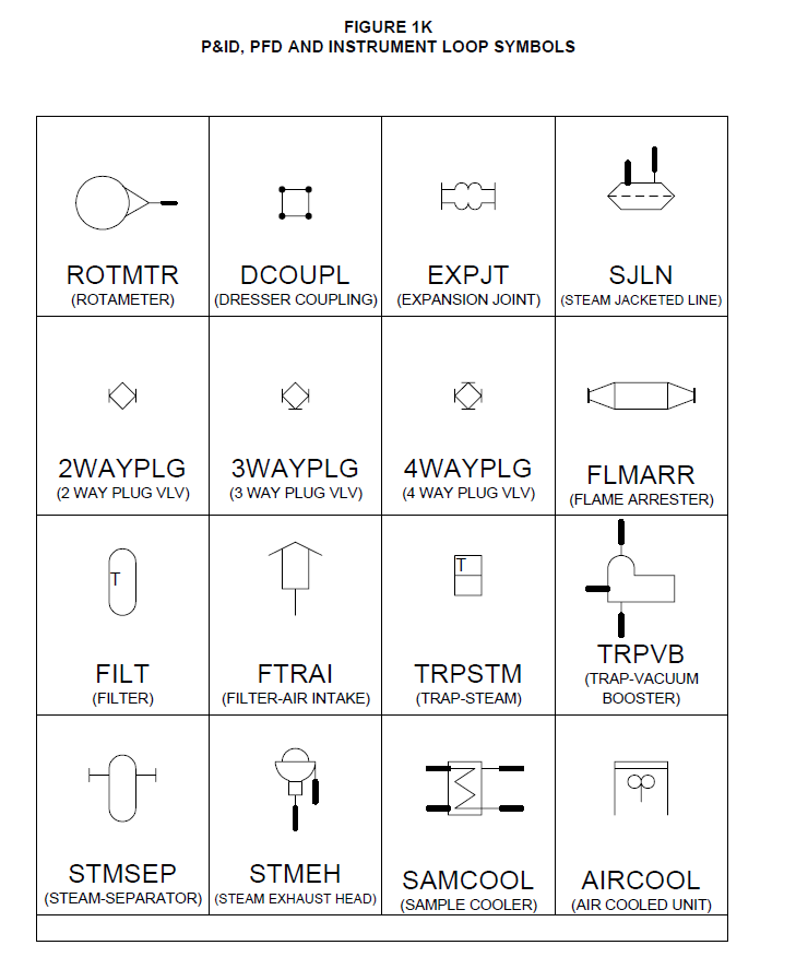
- This Practice covers the requirements for equipment, piping, and instrument symbols to be used on piping and instrumentation diagrams (P&ID’s), process flow diagrams (PFD’s) and instrument loop drawings.
- Any deviation to this Practice must be approved by the procedure described in EP 1–1–3.
- An asterisk (*) indicates that a decision by the Owner or Owner’s Engineer is required.
2.0 REFERENCES
The latest edition of the following publications are referred to herein.
STANDARDS AND PUBLICATIONS
DEFINITIONS
- ANSI - American National Standards Institute
- API - American Petroleum Institute
- CAD Supervisor - Inflection Point Engineering, LLC employee responsible for all CAD services and drawings at each plant.
- Instrument Loop Drawings - A drawing that shows all the hardwire and softwire, instruments junction boxes, and console or panel connections necessary for a control loop.
- Item (Equipment) Number - This number is the identification number for equipment. Typically, this number is site–specific. This number is equivalent to a Property Record (PR) numbering system used at various sites. Either Item Number or PR number may be used as applicable to local custom.
- ISA - Instrument Society of America
- Owner - Inflection Point Engineering, LLC
- Owner’s Engineer - A Inflection Point Engineering, LLC appointed engineer.
- P&ID - Piping and Instrumentation Drawing. A drawing that shows ALL equipment, piping, and instrumentation necessary for a given process.
- PFD - Process Flow Drawing. A drawing that shows only the major equipment, piping, and instrumentation necessary to describe the process.
- Property Equipment (PR) - This number is the identification number for equipment. Typically, this number is site–specific. This number is equivalent to an Item (Equipment) Number used at various sites. Either PR number or Item Number may be used as applicable to local custom.
GENERAL
- This Practice contains a general symbol library and seed files. The symbols have been selected from widely used national and industry standards. If additional symbols are required for a particular project, IPE review and approval as per EP 1–1–3 is required.
- The Owner’s symbol library is on the AutoCAD. A diskette can be provided upon request, from the Owner’s Engineer. Copies of the symbol cells are shown in the figures located in the back of this Practice.
- Copies of the AutoCAD seed files on diskettes will be furnished by the Owner upon request.
- A legend of graphic and text symbols shall be developed using the symbols shown in Figures 1 through Figure 4 for each site.
- Text shall be shown per Table 1.
DRAWING TYPES
- Piping and Instrumentation Drawing (P&ID)
- The P&ID shall be 24” x 36”.
- In general, all rotating equipment (pumps, compressors, blowers, etc.) shall be located near the bottom 1/3 of the drawings.
- All other equipment (drums, vessels, exchangers, condensers, etc.) shall be located near the top 2/3 of the drawing.
- All process piping lines shall enter or leave the drawing from the left or right edges of the drawing. Process piping lines are not permitted to be drawn that enter or leave the drawing from anywhere other than the left or right edges of the drawing.
- Lines entering a drawing unit shall have the drawing unit referenced from where it came from and PR or item number included in reference. Lines leaving the drawing unit shall reference the drawing to where the line is going.
- Whenever practical, all equipment related to a tower, drum or vessel shall be located on the same drawing (or be referenced) as the tower, drum, or vessel. However, equipment shall not be duplicated between drawings.
- All instrument symbols, identification and nomenclature shall conform to ISA–S5.1 and ISA– S5.3 and EP 12–1–1.
- The instrument tag number shall be a maximum of four alpha letters, derived from Tables 1 and 2 of ISA–S5.1, and a maximum of five digits.
- Equipment shall also include the additional information as shown in Table 3.
- As a minimum, the process and mechanical equipment information shall be shown on the P&ID as per Table 2 and Table 3.
- Appropriate AutoCAD layers and colors are shown in Table 4.
- Supplemental Instrument Loop, P&ID, and PFD Symbols shall be site–specific and shown per Table 5.
- Equipment identification (PR#) and names are site–specific and will be specified by the Owner’s Engineer.
- Supplemental information to be included with control valve, safety valve, and analyzer symbols are shown in Table 6.
- Process Flow Drawing (PFD)
- During the preliminary design, the process material balance and energy balance may be provided on separate sheets with the reference drawing number.
- After the process design is approved, the process material balance and energy balance shall appear on the approved PFD.
- As a minimum, process and mechanical equipment information shall be shown as noted for PFD’s in Table 2 and Table 3.
- The PFD shall be 24” x 36”.
- The general layout, symbols, and nomenclature used on the PFD is the same as for a P&ID. (Refer to Section 5.1.)
- Instrument Loop Drawings
- An instrument loop drawing shall be 11” x 17”.
- (*)Specific details for loop drawings shall conform to EP 12–1–1. Additional details are site– specific and shall be provided by the Owner’s Engineer.
6.0 TABLES
TABLE 1
TEXT STANDARDS FOR AUTOCAD DRAWINGS
| Drawing Type | Text Width Factor | Minimum Text Height | Notes | Standard File(4) |
|---|---|---|---|---|
| P&ID | 0.75 | 1/8” | (1), (2), (5) | PID.DWG |
| PFD | 0.75 | 1/8” | (1), (2), (5) | PFD.DWG |
| Instrument Loop | 0.75 | 1/8” | (1), (3), (5) | LOOP.DWG |
NOTE:
- All size variables set for 1” = 1” File.
- Drawing size is 24” x 36” for IPE format with attributes.
- Drawing size is 11” x 17” for IPE format with attributes. Format is divided into areas for field and panel.
- When starting a new drawing use the appropriate file name as your copy or prototype file.
- See EP 2–3–1 for text styles.
TABLE 2
PROCESS AND MECHANICAL P&ID DETAILS
| Equipment | Primary Identification | Detail Required(1) |
|---|---|---|
| Vessels/ Drums | Name PR and/or Item # Size (Overall dimensions, inside diameter, tangent to tangent) Design Temperature and Pressure |
Elevation of bottom tangent line above grade Vessel Internals: Type and number of trays in towers Type of internals in drums Insulated or not (include insulation code) Refractory lined or not Vessel trim |
| Reactors | Name PR or Item # Size (ID X T–T) Bed Depth Design Pressure and Temperature Maximum or P across bed |
Catalyst type Insulated or not (include insulation code) Refractory lined or not Vessel trim |
| Heat Exchangers | Name PR or Item # Surface Area Design Pressure and Temperature Duty Allowable Differential Pressure |
For Condensers and Reboilers, show elevation above grade. Insulated or not (include insulation code) |
| Fired Heaters | Name PR or Item # Coil Outlet Temperature Duty Maximum Outlet Temperature |
Insulated or not Refractory |
| Boilers | Name PR or Item # Steam Capacity Design Pressure Superheater Outlet Temperature |
---- |
TABLE 2
PROCESS AND MECHANICAL P&ID DETAILS (Cont’d)
| Equipment | Primary Identification | Detail Required(1) |
|---|---|---|
| Cooling Towers | Name PR or Item # Waterside Throughput (Operating) Inlet and Outlet Water Temperatures |
---- |
| Tanks | Name PR or Item # Size (diameter x height) Net Capacity Type (floating roof, cone roof, etc.) |
Surface area of any heaters Number and type of agitators or other mixing devices Capacity |
| Pumps/ Compressors | Name PR or Item # Rated Capacity Delta Pressure (P) Specific Gravity Type of Driver PR or Item # of Driver Horsepower Rating |
Warm–up (or cool–down) piping Cooling water piping arrangement Flushing piping arrangement Casing vent and drain piping Indicate drilled check valves, bypass piping, strainers, pressure relief valves |
| Steam Turbines | Name PR or Item # Steam Inlet Pressure & Temp. Steam Outlet Pressure & Temp. |
Warm–up piping Washing facilities Strainers, traps, and drains |
| Motors | Name PR or Item # Horsepower Rating Type Voltage |
---- |
TABLE 2
PROCESS AND MECHANICAL P&ID DETAILS (Cont’d)
| Equipment | Primary Identification | Detail Required(1) |
|---|---|---|
| Piping | <Refer to EP 5–1–5> Line size and rating (flange rating) Line number Piping material classification (symbol) Valve size if other than line size Each drawing shall include(2): Description of process or utility media entering and leaving (symbol) Flow rate of process media entering and leaving Continuous reference to subsequent drawings |
Bleeds associated with valves or between double block valves Chemical cleaning and flushing connections: Sample connections (indicate any heaters or coolers) Process drain and vent piping Temporary strainers and safety shields Utility Stations and Safety Showers(3) Location of “Figure-8”, Hamer, or other permanent blinds Line slope Car sealed valves Identification of valves for emergency isolation or shutdown, liquid pulldown, or vapor blowdown services Insulation or not (include insulation code) |
| Belt Conveyor | Rated Capacity Length Width Vertical Rise/Drop |
Elevation of head pulley |
| Screw Conveyor or Feed | Rated Capacity Length Screw Diameter |
----- |
NOTE:
- The information for pumps, compressors, and turbines shall be located at the bottom of the drawing under the appropriate equipment. The information for vessels, exchangers, tanks, columns, reactors, etc. shall be located at the top of the drawing over the appropriate equipment.
- Applies to PFD’s only.
- Applies to Utility Flow Diagrams only.
TABLE 3
P&ID EQUIPMENT IDENTIFICATION
| Equipment | Primary Identification | Units of Measure |
|---|---|---|
| General | Temperature | F |
| Pressure Area |
PSIG FT2 |
|
| Specific gravity (gas/liquid) | None | |
| Size | FT - IN | |
| Depth | FT - IN | |
| Length | FT - IN | |
| Width | FT - IN | |
| Heat Exchangers and Fired Heaters | Duty | MMBTU/HR |
| Boilers | Capacity (steam) | LB/HR |
| Cooling Towers | Water Throughput | GPM |
| Tanks | Capacity | gal or bbs (as appropriate) |
| Pumps | Capacity | GPM |
| Compressors | Capacity | SCFM |
TABLE 4
P&ID, PFD & LOOP AUTOCAD LAYERS
| Layer Name | Description | Color | Line Type | WT |
|---|---|---|---|---|
| Process | Process lines & text | Green | Cont. | .02 |
| Fire | Firewater lines & text | Red | Cont. | .02 |
| Air Water Steam |
Air lines & text Water lines & text Steam/Condensate Lines |
Blue Blue Red |
Cont. | .02 |
| Gas | Gas lines & text | Mag | Cont. | .02 |
| Equipment | Equipment lines & text | Yel | Cont. | .02 |
| Chemical | Caustic/Chemical lines & text | Cyan | Cont. | .02 |
| Instrument | Instrumentation lines | White | Cont. | .02 |
| Text | Other text | White | Cont. | .02 |
| General | IPE format lines Safety–Process Hazard Information Cutlines | White | Cont. | N/A |
TABLE 5
P&ID, PFD & INSTRUMENT LOOP SYMBOLS REFERENCES
| Site: | Reference Figures: |
|---|---|
| Plant | 1A through 1K |
TABLE 6
P&ID, PFD & INSTRUMENT LOOP SYMBOLS REFERENCES
| Instrument | Details Required |
|---|---|
| Control Valve | Size Failure position Bypass (if required) |
| Safety Valve | Inlet/Outlet size Orifice size Set point pressure Relief outlet destination |
| Analyzer | Component Component ranges |
© 2026 Inflection Point Engineering, LLC. All rights reserved. The content of this page — including calculation methods, reference data, written analysis, interactive tools, and source code — is the intellectual property of Inflection Point Engineering, LLC and is protected under applicable copyright, trademark, and trade secret laws. Unauthorized reproduction, redistribution, modification, or derivative use in whole or in part is prohibited without prior written consent.
Disclaimer. This material is provided for informational and educational purposes only and does not constitute professional engineering advice. Calculations, reference data, and methodologies are based on published standards and accepted engineering practice but are not a substitute for engineering judgment, site-specific analysis, or review by a licensed Professional Engineer. Inflection Point Engineering, LLC makes no warranties, express or implied, regarding the accuracy, completeness, or fitness for a particular purpose of any content presented here, and shall not be liable for any direct, indirect, incidental, or consequential damages arising from its use. Users assume all risk associated with applying this content to real-world design, operations, or decisions.
© 2026 Inflection Point Engineering, LLC. All rights reserved.